
HP Fabric Clustering System HP-UX Administrator's Guide, March 2008
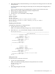
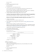
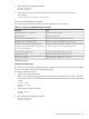
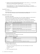
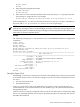
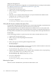

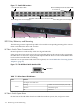

Figure 7-1 Switch LED Locations
HP Fabric Switch Cluster Connection LEDs
Console Port
Ethernet Management Port Status LEDs
Power Plug powers Power Supply 2
Power Plug powers Power Supply 1
Rear System Status LEDs
Front System Status LED
Power Supply 2 LED
Power Supply 1 LED
LED Color, Behavior, and Meaning
The following sections explain the possible colors and the corresponding meaning of the various
LEDs on the HP Fabric HCA and switches.
HP Fabric Switch Cluster Connection LEDs
Normal operation is indicated by solid color logical link LED.
If the connection from switch port to the corresponding HCA in the remote node is operational,
the LED shows as solid color. A physical link requires that the drivers on the attached HP Fabric
host have been installed and are running.
If the HCA is not operational and needs to be replaced, see “Install HP Fabric Clustering System
Adapters” (page 36).
Figure 7-2 The HP Fabric Switch Interface LEDs
link status
Switch LED location
Table 7-1 IB Port Status LED Indicators
FunctionColor
Per IB port status indicators.
Green
Valid Rx K-Char detected (Physical Link)Flashing
Link OK (Logical)Solid On
Link errorOff
HP Fabric Switch System Status
On the front of the HP Fabric Switch are LEDs that indicate system, fan, and power status.
110 Monitoring and Troubleshooting