
Implementing disaster recovery for HP Integrity Virtual Machines with Metrocluster and Continentalclusters on HP-UX 11i

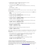
Table Of Contents
- Executive summary
- Introduction
- Audience
- Configuring Integrity Virtual Machines as packages in HP Metrocluster
- Verifying failover of Metrocluster packages across data centers
- Troubleshooting Metrocluster VM problems
- Application startup and monitoring
- Configuring Integrity Virtual Machines as packages in HP Continentalclusters
- Overview
- Software requirements for HP VMs in Continentalclusters
- Configuring HP VM packages in Continentalclusters
- Creating VM switches in all nodes of the primary cluster
- Configuring replicated storage for VM in Continentalclusters
- Installing the operating system on the virtual machine
- Testing the virtual guest OS in all nodes of the primary cluster
- Creating VM switches in all nodes of the recovery cluster
- Preparing the replicated storage for use in the recovery cluster
- Creating the virtual machine in all nodes of the recovery cluster
- Testing the virtual guest OS in all nodes of the recovery cluster
- Resynchronizing the replicated storage
- Packaging the HP VM in the primary cluster and the recovery cluster
- Creating a Continentalclusters package
- Creating a Continentalclusters configuration with the VM packages
- Running the Continentalclusters monitoring daemon in the recovery cluster
- Recovering to the recovery cluster
- Related documentation
- Appendix I
- Appendix II
- For more information
- Call to action

9
2. Create the device group pair for dgVM with the paircreate command:
# paircreate –g pkgA –f never –vl –c 15
to create volume pairs from Node1 [For fence level never]
3. To verify that the pair volumes are created with an appropriate fence level, run the following
command:
# pairdisplay –g dgVM
Creating an EMC Symmetrix device group
You need to create a device group on every node in the cluster. To create a device group, complete
the following steps:
1. Create the device group using the following command on each node on the R1 side (Node1 and
Node2).
# symdg –type RDF1 create dgVM
2. For each node on the R2 side (Node3 and Node4), create the device group.
# symdg –type RDF2 create dgVM
3. For each node on the R1 side (Node1 and Node2), assign the R1 devices to the device group.
# symld –sid 684 –g dgVM add dev 0015
# symld –sid 684 –g dgVM add dev 0016
4. For each node on the R2 side (Node3 and Node4), assign the R2 devices to the device group.
# symld –sid 130 –g dgVM add dev 0015
# symld –sid 130 –g dgVM add dev 0016
5. On each node on the R2 side (Node3 and Node4), associate the local Business Copy Volume
(BCV) devices to the R2 device group.
# symbcv –g dgVM add Dev 002C
# symbcv –g dgVM add dev 002D
6.
Establish the BCV devices using the following commands from the R2 side.
# symmir –g dgVM –full est
# symmir –g dgVM –full est
Steps 5 and 6 are optional. The use of BCV is recommended with all implementations of Metrocluster
SRDF. These BCV devices provide a good copy of the data when it is necessary to recover from a
rolling disaster.
7. Define a gatekeeper device for each device group, and associate this with the device group.
On each node on the R1 side (Node1 and Node2), enter the following commands:
# symgate –sid 684 define dev 0180
# symgate –sid 684 –g dgVM associate dev 0180
On each node on the R2 side (Node3 and Node4), enter the following commands:
# symgate –sid 130 define dev 00D8
# symgate –sid 130 –g dgVM associate dev 00D8
Creating a Continuous Access EVA data replication (DR) group
Use the HP StorageWorks Command View EVA user interface to create a DR group. For more
information on setting up Command View EVA for configuring, managing, and monitoring your
HP StorageWorks Enterprise Virtual Array storage system, refer to the HP Storage Works Command
View EVA Installation Guide and User Guide at
www.hp.com/support/manuals under the Storage
Software category.