
Implementing disaster recovery for HP Integrity Virtual Machines with Metrocluster and Continentalclusters on HP-UX 11i
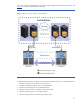

Table Of Contents
- Executive summary
- Introduction
- Audience
- Configuring Integrity Virtual Machines as packages in HP Metrocluster
- Verifying failover of Metrocluster packages across data centers
- Troubleshooting Metrocluster VM problems
- Application startup and monitoring
- Configuring Integrity Virtual Machines as packages in HP Continentalclusters
- Overview
- Software requirements for HP VMs in Continentalclusters
- Configuring HP VM packages in Continentalclusters
- Creating VM switches in all nodes of the primary cluster
- Configuring replicated storage for VM in Continentalclusters
- Installing the operating system on the virtual machine
- Testing the virtual guest OS in all nodes of the primary cluster
- Creating VM switches in all nodes of the recovery cluster
- Preparing the replicated storage for use in the recovery cluster
- Creating the virtual machine in all nodes of the recovery cluster
- Testing the virtual guest OS in all nodes of the recovery cluster
- Resynchronizing the replicated storage
- Packaging the HP VM in the primary cluster and the recovery cluster
- Creating a Continentalclusters package
- Creating a Continentalclusters configuration with the VM packages
- Running the Continentalclusters monitoring daemon in the recovery cluster
- Recovering to the recovery cluster
- Related documentation
- Appendix I
- Appendix II
- For more information
- Call to action
23
The VM Host ISO file that is used to install the OS into the guest is
/var/os/hpvm.0505_OE.Gold1.iso.
The guest virtual network device information consists of the following fields, separated by colons:
• Network
• Adapter-type—can be either
lan or avio_lan
• [Hardware-address] (optional)—formatted as
bus,device,mac-addr.
If you do not specify the hardware address, or a portion of it, the information is generated for you.
HP recommends allowing Integrity VM to generate the hardware address. The hardware address
consists of the following information:
–
bus (virtual network device PCI bus number)
–
device (virtual network device PCI slot number)
–
mac-addr (the virtual network device MAC address) in either of the following formats:
0xaabbcc001122 or aa-bb-cc-00-11-22
– The MAC address that you enter is checked to make sure it does not conflict with any of the VM
host’s physical network adapter MAC addresses.
• vswitch—virtual switch information is formatted as
vswitch:vswitch-name (where vswitch-name
is the name assigned to the virtual network switch when you create it using the
hpvmnet command)
Note: For online migration of a VM guest within a single Serviceguard cluster in a Continentalclusters environment, it is
required that the VM guest created in all the nodes of that cluster have the same “mac-addr” for each virtual network
device.
Installing the operating system on the virtual machine
Once the virtual machine is created, start the machine in any one of the nodes in the primary cluster
by going to its console. Let us consider Node1 for this example. Once the machine is started up,
install HP-UX 11i v3 on the virtual machine. During installation, provide IP address, the netmask, and
the default gateway information for this guest OS.
Testing the virtual guest OS in all nodes of the primary cluster
Once the operating system is installed, shut down the guest operating system and halt the virtual
machine in Node1. Log in to Node2 and import the volume group
vgvm and start the virtual machine
from this node. Check the status of the guest operating system. Once it is done, shut down the guest
operating system and halt the virtual machine.
Creating VM switches in all nodes of the recovery cluster
Create the VM switches in all nodes of the recovery cluster by issuing the following command.
#hpvmnet –c –S vs1 –n 0
Preparing the replicated storage for use in the recovery cluster
Once the virtual machines are tested in the primary cluster nodes, go to Node3 in the recovery cluster
and make the disks read/write by issuing the following command:
# pairsplit –I0 -g dgVM -rw
Creating the virtual machine in all nodes of the recovery cluster
The HPVM command
hpvmcreate is used to create a virtual machine. Import the volume group vgvm
and issue the following command in each and every node in the recovery cluster:
# hpvmcreate –Pcc_vm –a disk:scsi::lv: /dev/vgvm/rlvol1 \
–a network:lan:[hardware-address]:vswitch:vs1 \
–I cc_vm –O hpux