
HP-UX 11i v3 Crash Dump Improvements

Page 11
3.4.1 Hardware overlap across dump units
Performance tends to scale better when the hardware overlap (sharing of components such as
HBAs, links, targets) between paths to devices in different dump units is minimized.
For example, performance will generally be better when dump devices for separate dump units
are configured through separate target ports. Dumps generate large sequential writes which will
compete for bandwidth on the link and in the target controller. This issue is similar to the impact
of configuration ordering on HBA selection discussed in section 3.3, and can be resolved in a
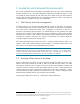
similar manner using lun path disabling. Figures 13 and 14 illustrate how this would work.
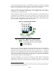
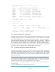
In the configuration example in Figures 13 and 14 there are two devices, two target ports, and
two HBA ports. Each HBA port has 2 paths to each device, one through each target. In Figure
13, Dev1 is configured first and a path is automatically selected through hba1, followed by the
configuration of Dev2 for which a path through hba2 is selected. The choice of paths through
separate HBA ports occurs automatically, as required by the auto-HBA-selection algorithm
described in section 3.3. If both auto-selected paths are through the same target (tgt1 in
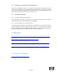
Figure 13) the administrator can disable one of the selected tgt1 paths to balance the dump units
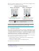
across the targets. The result of disabling the hba2–tgt1–Dev2 path is shown in Figure 14. After
disabling this path, Dev2 will be auto-reconfigured via the only other hba2 path available to
Dev2, which is through tgt2, thus balancing the dump units across the available targets.
3.4.2 Compression/parallelism tradeoffs
Compressed dump reduces the size of the data in memory by compressing it before writing it to
disk. The compression ratio (ratio of the size of data pre-compression to post-compression)
depends on the data pattern in memory (e.g., whether the data is fairly random or not). As a
result the compression ratio can vary for different memory areas that are dumped, and therefore
in parallel dump one dump unit may have a different compression ratio from another. This leads
to imbalances in the size of the post-compression data of various dump units, even though the
actual memory area to be dumped has been evenly distributed. Since the overall dump time is
Both dump units are configured with
paths through the same target (tgt1).
Figure 13 – Redundant target
configuration
Figure 14 – Balancing paths
across targets
After disabling the hba2
–
tgt1
–
Dev2 path each
dump unit is configured on a separate target.
D1
D2
(black line)
=
Unused path
(red line)
=
Configured dump path
tgt2
tgt1
Dev2
hba2
hba1
Dev1
D1
D2
tgt2
tgt1
Dev2
hba2
hba1
Dev1
(blue line)
=
Disabled path