
HP-UX 11i v3 Crash Dump Improvements


Page 8
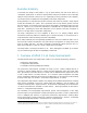
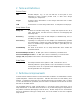
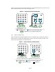
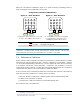
Figures 8 and 9 combine elements of each of the above examples to illustrate more complex sets
of devices and dump units.
Figure 8 shows an uncompressed example with 2 legacy devices, 4 reentrant devices through 3
HBA ports, and 2 concurrent devices. The two legacy devices are assigned to one dump unit; the
two concurrent devices each get assigned to an additional dump unit; and the four reentrant
devices are assigned to three additional dump units (one for each of their 3 HBA ports). This
results in a total of 6 dump units. The Device Parallelism formula in section 3.1.3 can be usefully
applied here.
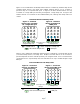
Figure 9 shows a compressed dump with 2 reentrant devices through 1 HBA port, and 3
concurrent devices. In this case the Device Parallelism supports 4 dump units (3 for the concurrent
devices + 1 for the reentrant devices), but the CPU Parallelism in a 16-CPU system will only
support 3 compressed dump units.
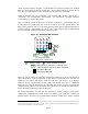
3.3 Automatic HBA Selection
When a dump device is configured a path to the device is automatically selected by the dump
infrastructure in a manner which balances the configured dump devices across the available HBA
ports. The purpose is to make the HBA assignments in a manner which maximizes parallelism.
This occurs at run-time, when a dump device is configured, not at dump time.
During dump device configuration a path to the device is chosen through an HBA port which has
not been used by previously configured dump devices, where possible. If all available HBA ports
have been used then an HBA port which has the least number of devices configured on it will be
Compressed Dump
(3 Dump Units,
5 dump devices)
= available CPUs = CPUs used during dump
= legacy dump device
= reentrant dump device
= concurrent dump device
= HBA port
Uncompressed Dump
(6 dump units,
8 dump devices)
D1
D2
D3
D4
D5
D6
D1
D2
D3
Figure 8 – Complex
Uncompressed Example
Figure 9 – Complex
Compressed Example