Using HP-UX VLANs HP 9000 Networking for HP-UX 11i Manufacturing Part Number: T1453-90001 E0302 U. S. A. © Copyright 2002 Hewlett-Packard Company.
Legal Notices The information in this document is subject to change without notice. Hewlett-Packard makes no warranty of any kind with regard to this manual, including, but not limited to, the implied warranties of merchantability and fitness for a particular purpose. Hewlett-Packard shall not be held liable for errors contained herein or direct, indirect, special, incidental or consequential damages in connection with the furnishing, performance, or use of this material. Warranty.
Contents 1. What are HP-UX VLANs? HP-UX VLAN Features . . . . . . . . . . . . . . . . . . . . . . . . . . . . . . . . . . . . . . . . . . . . . . . . . . Benefits of HP-UX VLANs. . . . . . . . . . . . . . . . . . . . . . . . . . . . . . . . . . . . . . . . . . . . . . . . Types of VLANs Supported by HP-UX . . . . . . . . . . . . . . . . . . . . . . . . . . . . . . . . . . . . . . HP-UX VLAN Tagging. . . . . . . . . . . . . . . . . . . . . . . . . . . . . . . . . . . . . . . . . . . . . . . . . . .
Contents Using lanadmin to Delete a VLAN . . . . . . . . . . . . . . . . . . . . . . . . . . . . . . . . . . . . . . . 52 A. Troubleshooting Diagnostic Flowcharts . . . . . . . . . . . . . . . . . . . . . . . . . . . . . . . . . . . . . . . . . . . . . . . . . . . Flowchart 1: Link Level Tests . . . . . . . . . . . . . . . . . . . . . . . . . . . . . . . . . . . . . . . . . . . . . Flowchart 1a: Linkloop Test. . . . . . . . . . . . . . . . . . . . . . . . . . . . . . . . . . . . . . . . . . . . .
Tables Table 1-1. Needed Patches for HP-UX VLANs . . . . . . . . . . . . . . . . . . . . . . . . . . . . . . Table 2-1. Summary of VLAN Tagging Assignment . . . . . . . . . . . . . . . . . . . . . . . . . Table 2-2. Allowable Values for Parameters in vlanconf File . . . . . . . . . . . . . . . . . . Table 2-3. ToS to 802.1 User Priority Mappings Based on IP Precedence . . . . . . . . Table 2-4. Allowable Settings for VLAN_PRI_OVERRIDE Value in vlanconf File . Table 2-5.
Tables 6
Figures Figure 1-1. VLANs (Virtual LANs) . . . . . . . . . . . . . . . . . . . . . . . . . . . . . . . . . . . . . . . Figure 1-2. IEEE 802.1Q VLAN Tag in Ethernet Frame. . . . . . . . . . . . . . . . . . . . . . Figure 1-3. VLANS Overlapping or Sharing the Same LAN Card Port . . . . . . . . . . Figure 2-1. Communication between VLANS Requires an External Router . . . . . . Figure 2-2. Tagged and Untagged VLAN Technology in Same Network . . . . . . . . . Figure 2-3. VLANs and Service Guard . . . . . . . . .
Figures 8
1 Chapter 1 What are HP-UX VLANs? 9
What are HP-UX VLANs? A Virtual LAN (VLAN) is a logical or virtual network segment that can span multiple physical network segments. Using VLANs, you can group switched-network end-stations by: • department, such as engineering and manufacturing, • type of user, such as power users or those with special needs, • application, or • project instead of physical location (Figure 1-1).
What are HP-UX VLANs? VLANs create broadcast domains using switches instead of routers. While VLANs in some environments may reduce the number of routers needed (and their latency), you still need a router if you want the VLANs to communicate with each other.
What are HP-UX VLANs? HP-UX VLAN Features HP-UX VLAN Features Following are some of the features of HP-UX VLANs: 12 • HP-UX VLANs are implemented with host-based IEEE 802.1Q/p compliant tagging to allow configuring multiple VLANs on a given Ethernet LAN card based on their IP-subnet, protocol, or LAN card port. • HP VLANs are for use over fast Ethernet or gigabit Ethernet LAN cards running on HP-UX 11i (11.11) PA-RISC-based servers and workstations. HP-UX supports up to 1024 VLANS per LAN card port.
What are HP-UX VLANs? Benefits of HP-UX VLANs Benefits of HP-UX VLANs The advantages of HP-UX VLANs are: Chapter 1 • Physically dispersed workgroups can be logically connected within the same broadcast domain to appear as if they are on the same physical LAN. • A single physical link can simultaneously serve several IP subnets when subnet-based VLANs are configured on that link. • Switches no longer need to classify and tag traffic. They focus on forwarding packets.
What are HP-UX VLANs? Types of VLANs Supported by HP-UX Types of VLANs Supported by HP-UX The types of HP-UX VLANs that you can create are as follows: • NIC-Port Based--A group of physical LAN card ports belong to the same layer-2 broadcast domain. Each LAN card port transmits and receives frames belonging to the VLAN associated with that port. Members of the same port-based VLAN all have the same VLAN ID. A VLAN ID uniquely identifies the VLAN to which a frame belongs.
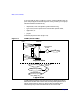
What are HP-UX VLANs? HP-UX VLAN Tagging HP-UX VLAN Tagging Network switches and end stations that know about VLANs are said to be VLAN-aware. Network switches and end stations that can interpret VLAN tags are said to be VLAN-tag-aware. HP-UX VLAN-tag-aware end stations add VLAN tags to standard Ethernet frames--a process called explicit tagging.
What are HP-UX VLANs? HP-UX VLAN Tagging Figure 1-3 VLANS Overlapping or Sharing the Same LAN Card Port Server HP Gigabit or Fast Ethernet LAN Card Port VLAN0 16 VLAN1024 Chapter 1
What are HP-UX VLANs? System and Software Requirements System and Software Requirements Following are the hardware and software requirements for VLANs as of March 2002: • Type of HP System Required — HP-UX Precision Architecture (PA-RISC). • OS Required — HP-UX 11i (11.11). New HP servers and workstations shipped after March 2002 already have VLAN technology pre-installed in the operating environment.
What are HP-UX VLANs? System and Software Requirements Table 1-1 Needed Patches (Continued)for HP-UX VLANs (Continued) Driver 11i Patch # SAM PHCO_25866 * Either the 100Base-T or Gigabit patch may be optional depending on which link type you have.
What are HP-UX VLANs? Supported Switches Supported Switches HP-UX VLANs are supported with switches that implement IEEE 802.1Q-compliant VLAN tagging. The switches must implement at least port-based VLANs and must be VLAN-tag aware.
What are HP-UX VLANs? Unsupported Functionality Unsupported Functionality HP-UX VLANs do not support the following functionality: • GARP VLAN registration protocol (GVRP) is currently not supported. HP-UX VLANs will not send GVRP messages or interpret them. • HP-UX VLANs do not operate on: — Any Itanium-based servers whether the LAN card is factory installed or customer installed. — HP-UX 11.20, 11.0, and 10.20. — FDDI, Token Ring, ATM, 100VG, EISA, and HP-PB LAN cards.
2 Chapter 2 Overview of Installation and Configuration 21
Overview of Installation and Configuration Planning HP-UX VLANs Planning HP-UX VLANs The following requirements must be satisfied before setting up VLANs in an HP-UX network: • In order for both end stations of a VLAN to communicate, both the end-station LAN cards and the switch ports that are connected to those LAN cards on a point-to-point link need to be VLAN-tag-aware. • For VLANs to communicate with each other, an external VLAN-aware switch or router is required (Figure 2-1).
Overview of Installation and Configuration How to Configure VLANs on the Switch How to Configure VLANs on the Switch IEEE 802.1Q compliant devices and legacy/untagged VLANs can coexist on the same networks, but legacy/untagged VLANS require a separate link, whereas the 802.1Q tagged VLANs can combine several VLANs into one link. On 802.1Q-compliant devices, separate ports (configured as untagged) must be used to connect separate VLANs to non-802.1Q devices.
Overview of Installation and Configuration How to Configure VLANs on the Switch Table 2-1 Summary of VLAN Tagging Assignment VLANs Per Port Tagging Scheme 1 Untagged or Tagged. If the device connected to the port is 802.1Q-compliant, then the recommended choice is “Tagged.” 2 or more 1 VLAN Untagged; all others Tagged or All VLANs Tagged A given VLAN must have the same VLAN ID on any 802.1Q-compliant device in which the VLAN is configured.
Overview of Installation and Configuration How to Configure VLANs on HP-UX How to Configure VLANs on HP-UX Choose Configuration Method: Use SAM; Edit vlanconf; Use lanadmin There are three ways to configure VLANs: the first two methods preserve configuration changes across reboots; the third applies changes immediately but doesn’t preserve configuration changes across reboots: To permanently save your configurations, you can either: • Use the GUI-based system admin manager (SAM).
Overview of Installation and Configuration Configuration Process Configuration Process Following are the steps to configure HP-UX VLANs. These steps are for defining VLAN membership, assigning names, VLAN IDs, and port assignments. This procedure assumes that the switches can add VLAN tags: 1. Determine the network topology affected. Either draw the affected network topology or list it. Include all affected end stations--workstations and servers. 2. Define the VLANs.
Overview of Installation and Configuration Properties of a VLAN Properties of a VLAN When a VLAN is created on a given LAN card port, (see “Creating a VLAN”), the system generates a virtual PPA or VPPA which can be used to send and receive 802.1Q tagged frames on that LAN card. Each HP-UX VLAN has a Virtual PPA associated with it. A VPPA has essentially the same properties as a physical point of attachment (PPA) on a LAN card. The differences are: 1.
Overview of Installation and Configuration Special Case of VLAN ID 0--Priority Tagged Frames Special Case of VLAN ID 0--Priority Tagged Frames VLAN ID 0 means that the frame doesn’t belong to any VLAN but has 802.1p priority information. Ensure that any switches used with HP-UX VLANs support VLAN ID 0. Promiscuous Mode Characteristics Only one stream can be running in unfiltered promiscuous mode per physical interface plus all its VLAN interfaces put together.
Overview of Installation and Configuration Allowable Values for HP VLANs Allowable Values for HP VLANs Table 2-2 lists the allowable values for configuring VLANs in the /etc/rc.config.d/vlanconf file. It describes the parameter functions, default values, and allowable ranges. For the format of the /etc/rc.config.d/vlanconf file, refer to “Configuring VLANs by Editing vlanconf File” in this document.
Overview of Installation and Configuration Allowable Values for HP VLANs Table 2-2 Parameter -description 1 30 Allowable Values for Parameters in vlanconf File (Continued) Range and Restrictions Default Type Default is an empty string; lanadmin will display it as UNNAMED.
Overview of Installation and Configuration Using VLANs with MC/ServiceGuard Using VLANs with MC/ServiceGuard You can create MC ServiceGuard fail-over groups with VLANs as long as the primary and standby links are both VLAN interfaces with the same VLAN ID. See Figure 2-2 for an example. Please refer to HP MC ServiceGuard documentation for more details.
Overview of Installation and Configuration How is 802.1p Priority Set? How is 802.1p Priority Set? IP packets are classified and marked into different priority levels and the markings are transported through a type of service (ToS) octet in the IPv4 header and a traffic class field in the IPv6 header. HP-UX end stations transmit IPv4 type-of-service (ToS) values but do not enforce priority. The end stations perform ToS-to-802.
Overview of Installation and Configuration How do Pri and ToS Override Affect My Inbound and Outbound frames? How do Pri and ToS Override Affect My Inbound and Outbound frames? Consider the following command. lanadmin -V create vlanid VID pri PRI tos TOS pri_override PO tos_override TO 6 This command will create a VLAN interface on PPA 6, with VID as the VLAN ID, PRI as the 802.1p priority, TOS as the IPv4 ToS value. • All frames transmitted via the newly created interface will be VLAN tagged.
Overview of Installation and Configuration How do Pri and ToS Override Affect My Inbound and Outbound frames? Table 2-4 Allowable Settings for VLAN_PRI_OVERRIDE Value in vlanconf File (Continued) Priority Override Setting Outbound IP Packets CONF_TOS VLAN Tag priority comes from ToS to 802.1p mapping table (see Table 2-3). The ToS value used is TOS.
Overview of Installation and Configuration Setting 802.1p Priority, ToS, and Overrides Setting 802.1p Priority, ToS, and Overrides 802.1p priority is the priority in the tag in the frame header. Switches can use the 802.1p priority. ToS is the IP precedence in the IP header. Switches ignore ToS. Routers may use it. The Priority Override Levels for Outbound Traffic are as follows: CONF_PRI IP_HEADER CONF_TOS Your specified priority will be used. IP header ToS will be converted to 802.1p priority.
Overview of Installation and Configuration Where to Get More Information 36 Chapter 2
3 Chapter 3 Configuring VLANs Using SAM 37
Configuring VLANs Using SAM Configuring VLANs Using SAM Configuring VLANs Using SAM You can use SAM to configure VLANs by completing the following steps: 1. Log in as root. 2. Check the HP-UX version by typing: uname -a. The version should be HP-UX 11i (11.11) 3. At the HP-UX prompt, type: sam 4. At the SAM main window, double click: Networking and Communications 5. There are then 2 ways to access VLAN configuration.
Configuring VLANs Using SAM Configuring VLANs Using SAM 6. On the Virtual LAN screen, available VLAN-aware cards are displayed. When you select a LAN card and then use the Create VLAN pulldown (Figure 3-2), the Create VLAN screen appears (Figure 3-3). For the VLAN ID, enter any number between 0 and 4094 and use it only once within that port. NOTE Figure 3-2 The VLAN ID is not the same as the number of VLANs supported --HP-UX supports up to 1024 VLANS per LAN card port.
Configuring VLANs Using SAM Configuring VLANs Using SAM Figure 3-3 Create Virtual LANs After you have assigned a VLAN ID, the VLAN then shows on the main screen with the status Not Configured. You then highlight the VLAN, and select the Configure IP Address pulldown action. This displays the Add an IP Address for the VLAN screen (Figure 3-4). After you have configured an IP address for the VLAN, its status on the main screen will show as Enabled. Assign VLAN IDs to each VLAN.
Configuring VLANs Using SAM Configuring VLANs Using SAM On the Modify VLAN Properties screen, the fields are all optional; the data elements are the same as discussed in the chapter “Overview of Installation and Configuration:” VLAN name, VPPA, priority, ToS, and overrides. Figure 3-4 Add an IP Address for the VLAN 7. At any time, view the online help pulldown menu for doing any of the listed tasks or for finding help on a specific field.
Configuring VLANs Using SAM Configuring VLANs Using SAM 42 Chapter 3
4 Chapter 4 Configuring VLANs by Editing vlanconf File 43
Configuring VLANs by Editing vlanconf File Modifying Parameters in vlanconf File Modifying Parameters in vlanconf File Following is the format of the /etc/rc.config.d/vlanconf file. To permanently save changes to this file, either use SAM or use a text editor such as “vi.” If you use the lanadmin command line interface to make changes to VLANs, your configuration will not be preserved after reboots unless you modify the vlanconf file manually.
Configuring VLANs by Editing vlanconf File Modifying Parameters in vlanconf File # priority. Only for # IP packets. For non-IP # packets, CONF_PRI # will be used. # CONF_TOS - User specified ToS, taken # from VLAN_TOS[] will be # converted to # 802.1p priority. # # VLAN_TOS_OVERRIDE : Inbound ToS value to be used for IP # packets. # Allowed ToS override levels are as follows: # # IP_HEADER - ToS value in the IP # header will be used # (default if not # specified). # ETHER_HEADER - Ether header 802.
Configuring VLANs by Editing vlanconf File Modifying Parameters in vlanconf File # # # # # # # VLAN_ID[1]= VLAN_PRIORITY[1]= VLAN_TOS[1]= VLAN_PRI_OVERRIDE[1]= VLAN_TOS_OVERRIDE[1]= VLAN_NAME[1]=”” VLAN_VPPA[1]= Example: Following is an example where the physical interface lan0 has been assigned a VLAN ID of 1, default values for VLAN priority, VLAN ToS, VLAN priority override, VLAN ToS override, the name “Red,” and a VLAN PPA of 5000.
Using lanadmin -V to Administer VLANs 5 Chapter 5 Using lanadmin -V to Administer VLANs 47
Using lanadmin -V to Administer VLANs Using the lanadmin -V Command for Administering VLANs Using the lanadmin -V Command for Administering VLANs To configure VLANs, you use either the GUI-based system admin manager (SAM) or edit the configuration file with an editor. VLAN configuration doesn’t require a reboot to take effect. If you use SAM, your configurations will be preserved after reboots in a configuration file called /etc/rc.config.d/vlanconf.
Using lanadmin -V to Administer VLANs Using the lanadmin -V Command for Administering VLANs -V -V -V -V CONF_TOS or CONF_PRI) [pri_override (CONF_PRI,IP_HEADER or CONF_TOS)] scan info basevppa help Using lanadmin to Create a VLAN Assume that the system has the following configuration as shown by the lanscan command output.
Using lanadmin -V to Administer VLANs Using the lanadmin -V Command for Administering VLANs The VLAN (lan5000) appears in lanscan output just like a physical interface. VPPAs are identified by the string “VLANx” in the hardware path, where x is a number and is unique per VPPA. In the lanscan output, VPPAs of a given physical interface are displayed just after the corresponding physical interface. The verbose option of the lanscan command displays more information about the VLAN.
Using lanadmin -V to Administer VLANs Using the lanadmin -V Command for Administering VLANs Querying for a Single VPPA on a System You can query the Virtual PPA using the following command: lanadmin -V info The info command will return the output in the following format when successful.
Using lanadmin -V to Administer VLANs Using the lanadmin -V Command for Administering VLANs lanadmin -V modify vlanid 53 pri 3 5000 Successfully modified lan5000 Old value: vlanid 454 pri 6 New value: vlanid 53 pri 3 After the modification, the lanscan -v output will display: Hardware Station Crd Hdw Net-Interface NM MAC HP-DLPI DLPI Path Address In# State NamePPA ID Type Support Mjr# VLAN0 0x001083FF9951 5000 UP lan5000 snap5000 14 ETHER Yes 119 Extended Station LLC Encapsulation Address Methods 0x001083FF
Using lanadmin -V to Administer VLANs Using the lanadmin -V Command for Administering VLANs lanadmin -V delete 5000 The lanadmin -p , command always displays the displays the applications and commands that use or are configured on the interface. Lets take another example.
Using lanadmin -V to Administer VLANs Using the lanadmin -V Command for Administering VLANs 54 Chapter 5
A Appendix A Troubleshooting 55
Troubleshooting This chapter provides guidelines for troubleshooting VLANs. It contains the following sections: 56 • Diagnostic Flowcharts. • Use of lanadmin and lanscan commands and scripts for testing or troubleshooting VLANs.
Troubleshooting Diagnostic Flowcharts Diagnostic Flowcharts Table A-1 summarizes the types of network tests in the diagnostic flowcharts. Follow the flowcharts in sequence beginning with Flowchart 1. Table A-1 Flowchart Descriptions Chart Type of Test Purpose 1 Link Level Tests Checks communications between link levels. Verifies VLAN creation. 1a linkloop Test Verifies link-level address of remote hosts. 1b lanscan, lanadmin Tests Verifies VLAN IDs and tests VLAN creation.
Troubleshooting Flowchart 1: Link Level Tests Flowchart 1: Link Level Tests Check communications between link levels on the source and target host using the linkloop , lanscan, and lanadmin commands. The source interface should be a VPPA, that is, a PPA corresponding to a VLAN interface. The destination MAC address is the remote VPPA’s MAC address.
Troubleshooting Flowchart 1: Link Level Tests Figure A-1 Flowchart 1 Link Level Tests linkloop Test lanscan and lanadmin Tests Appendix A 59
Troubleshooting Flowchart 1: Link Level Tests Flowchart 1a: Linkloop Test Figure A-2 Flowchart 1a Linkloop Test Execute linkloop to remote host Linkoop successful? YES Network-Level Tests NO Loopback FAILED; Address has bad format or Not an individual address Loopback FAILED; remote host fails to respond Re-check remote host address and if same VLAN ID is enabled, choose a different remote host and re-execute linkloop Correct the link address parameter Linkoop successful? Link Level Test NO lans
Troubleshooting Flowchart 1: Link Level Tests Flowchart 1a Procedures • Execute linkloop to remote host. If linkloop is successful, continue to Network Test. Else if linkloop fails note which error was returned. • If loopback failed error = “Address has bad format” or “not an individual address” then correct the link level address with the proper station address format/value and repeat the Link Level Test. • Otherwise, loopback failed because the remote host did not respond.
Troubleshooting Flowchart 1: Link Level Tests Flowchart 1b: lanscan and lanadmin Test Figure A-3 Flowchart 1b lanscan and lanadmin Test Is your interface displayed after executing lanscan? YES YES Network-Level Tests NO NO Create VLAN by running lanadmin -V create YES Problem fixed? YES Stop 62 Run Execute lanscan -v Is VLAN ID correct? Modify VLAN by running lanadmin -V modify NO Any errorYES messages? NO Network-Level Tests YES Correct the problem Appendix A
Troubleshooting Flowchart 1: Link Level Tests Flowchart 1b Procedures • Execute lanscan command and verify your interface is displayed by the system. — If it is displayed, run lanscan -v to ensure the VLAN ID is correct. If so, return to the network Test. If not, modify the VLAN to the correct one by running the command lanadmin -V modify. — If the interface is not displayed, run lanadmin -V create to create the VLAN. • If the problem is fixed, Stop. Else, check for any error messages.
Troubleshooting Flowchart 2: Network Level Tests Flowchart 2: Network Level Tests Figure A-4 Flowchart 2 Network Level Tests ARP Test ping Test 64 Appendix A
Troubleshooting Flowchart 2: Network Level Tests Flowchart 2 Procedures Appendix A • See Flowchart 2a to validate ARP entries and remote host availability. • See Flowchart 2b to check communication between network layers on source and target host using ping.
Troubleshooting Flowchart 2: Network Level Tests Flowchart 2a: ARP Test Figure A-5 Flowchart 2a ARP Test Is remote host entry in ARP cache? NO Remote host up? YES NO YES Bring up remote host Is the ARP entry correct and complete ? NO Use ARP to correct and complete the entry YES ping Test 66 Appendix A
Troubleshooting Flowchart 2: Network Level Tests Flowchart 2a Procedures Appendix A • Use ARP to verify that an entry exists for the remote host in your system's ARP cache by executing arp hostname • If there is no ARP entry for the remote host, check to see if the remote host is up. If not, bring up remote host and continue to ping Test. • If the ARP entry is incorrect or not complete, use ARP to enter the correct station address of the remote system and continue to ping Test.
Troubleshooting Flowchart 2: Network Level Tests Flowchart 2b: ping Test Figure A-6 Flowchart 2b ping Test Execute ping remotehost YES ping successful? NO Validate network, remote host, and configuration settings YES Stop 68 continued Appendix A
Troubleshooting Flowchart 2: Network Level Tests Flowchart 2b Procedures Appendix A • Execute ping to remote host using ping. • If ping is successful, stop. If not, validate network, remote host, and configuration settings. Verify the routing tables using the netstat -rn command.
Troubleshooting Flowchart 2: Network Level Tests Flowchart 2b (continued): Figure A-7 Flowchart 2b (continued) ping not successful YES Network unreachable? error? Network-Level Tests NO No response from ping? YES Link-Level Tests NO Unknown host error? YES Correct BIND, YP, or /etc/hosts configuration NO No route to host error? ping Test YES Add route table entry NO Call HP 70 Appendix A
Troubleshooting Flowchart 2: Network Level Tests Flowchart 2b (continued) Procedures Appendix A • If network unreachable error, go to the Configuration Tests. • If no response from ping, validate switches in path support VLANs and remote host supports them as well. Otherwise, reconfigure network path, or configure VLANs on remote host and/or switches then repeat ping Test. Return to linkloop test. • If you receive an unknown hosts error, add the missing host name and repeat ping Test.
Troubleshooting NetTL Trace and Log of VLANs NetTL Trace and Log of VLANs The nettl tool can be used to troubleshoot VLANs. Following is a sample trace output from a Gigabit Ethernet card: Tracing Output from a Gigabit Ethernet Card ^^^^^^^^^^^^^^^^^^^^^^Gigabit Ethernet LAN/9000 Networking^^^^^^^^^^^^^^^^^^ Timestamp : Wed Nov 07 PST 2001 11:08:03.
Troubleshooting NetTL Trace and Log of VLANs Device ID : 1 Path ID : -1 Connection ID : 0 Location : 00123 ~~~~~~~~~~~~~~~~~~~~~~~~~~~~~~~~~~~~~~~~~~~~~~~~~~~~~~~~~~~~~~~~~~~~~~~~~~~~ Received 1480 bytes via Ethernet Wed Nov 07 11:08:03.961449 PST 2001 pid=[ICS] interface=[1] Dest: 00-10-83-05-16-7d Source: 00-10-83-05-16-7e 00-10-83-05-16-7e VLAN Tag: 0x4004 0: 45 00 05 b6 be 49 40 00 ff 01 21 8a 65 03 66 2f E....I@...!.e.f/ 16: 65 03 66 3d 00 00 77 9c 71 c9 00 02 3b e9 86 6d e.f=..w.q...;..
Troubleshooting NetTL Trace and Log of VLANs 74 Appendix A
Glossary 802.1p: IEEE Standard supplement, now incorporated in IEEE 802.1D. Defines 8 priority levels for traffic classification at the data link level and suggests how they might be used. 802.1Q: IEEE Standard that specifies the architecture for VLAN tagging, association, and VLAN-capable bridges. 100Base-T: A 100 Mbit/s communication method specified in the IEEE 802.3u-1995 standard. The official name for Fast Ethernet. Alias: Name of the interface that corresponds to a given Internet address on a system.
Glossary IP: IP: Internet protocol. IP Address: See Internet Address glossary entry. LAN: See Local Area Network. Local Area Network (LAN): A data communications system that allows a number of independent devices to communicate with each other. Local Network: The network to which a node is directly attached. Maximum Transmission Unit (MTU). Largest amount of data that can be transmitted through that interface. This value does not include the LLC or MAC headers. NetTL.
Glossary VPPA: Virtual PPA or VPPA: Virtual Interfaces which are dynamically created by you (using lanadmin or SAM). The interfaces are “virtual” because they do not have a unique hardware instance. A virtual PPA is the PPA associated with a VLAN. VLAN: Virtual LAN.VLANs, are a mechanism to determine which end stations should receive broadcast traffic, since it should not be sent arbitrarily to every connected user. Each packet transmitted by an end-station is assigned to a VLAN.
Glossary Virtual PPA or VPPA: 78 Glossary