
NetWare 4.1/9000 Print Services

B-12
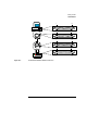
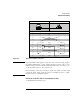
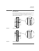
Cabling Printers
Optimal Serial Cabling
The printer sends XON/XOFF data through this pin which connects to Pin 2 on a
9-pin connector and Pin 3 on a 25-pin connector on the PC. The printer uses Pin
2. This attaches the printer's transmit pin to the PC's receive pin.
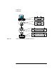
2 RXD (Receive Data input pin)
The printer receives data (the print job) through this pin which connects to Pin 3
on a 9-pin connector and Pin 2 on a 25-pin connector on the PC. The printer uses
Pin 3. This attaches the PC's transmit pin to the printer's receive pin.
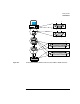
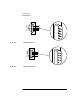
3 RTS (Request To Send output pin)
The signal level for Pin 4 is always high as long as the printer is on. This signal
can be used as a source of a high signal level to enable certain functions on some
printers. We recommend that you tie (solder) Pin 4 to Pins 5, 6, and 8 on the
printer; however, this may not work if your printer uses these pins differently.
4 CTS, DSR, and DCD (Clear To Send, Data Set Ready, and Data Carrier Detect
input pins, respectively)
One or more of these pins may be used to enable certain functionality on the
printer. We recommend that you tie (solder) these pins to Pin 4 on the printer to
maintain a high signal level (see note 12).
5 DTR (Data Terminal Ready output pin)
The printer often uses this pin for the hardware handshaking signal. If the printer
supports DTR handshaking, it should use Pin 20. However, some printers use
Pins 11 or 19 (or other pins besides Pin 20) to implement their handshaking.
The handshaking pin should be connected to Pin 8 on a 9-pin connector and Pin
5 on a 25-pin connector on the PC (and also Pin 6 on either connector if you
followed the recommendation in note 5).