Installing and Administering HP FDDI/9000 Software Edition 4 J2157-90013 HP 9000 Networking 05/97 Printed in: U.S.A. 1997 Hewlett-Packard Company. All rights reserved.
Legal Notices The information in this document is subject to change without notice. Hewlett-Packard makes no warranty of any kind with regard to this manual, including, but not limited to, the implied warranties of merchantability and fitness for a particular purpose. Hewlett-Packard shall not be held liable for errors contained herein or direct, indirect, special, incidental or consequential damages in connection with the furnishing, performance, or use of this material. Warranty.
©copyright 1980, 1984, 1986 Novell, Inc. ©copyright 1986-1992 Sun Microsystems, Inc. ©copyright 1985-86, 1988 Massachusetts Institute of Technology. ©copyright 1989-93 The Open Software Foundation, Inc. ©copyright 1986 Digital Equipment Corporation. ©copyright 1990 Motorola, Inc.
Contents 1. FDDI Resources HP-UX Manual Reference Pages . . . . . . . . . . . . . . . . . . . . . . . . . . . . . . .14 Logging and Tracing Messages . . . . . . . . . . . . . . . . . . . . . . . . . . . . . . . . .16 Manual Installation and Configuration . . . . . . . . . . . . . . . . . . . . . . . . . .18 HP FDDI Device Files . . . . . . . . . . . . . . . . . . . . . . . . . . . . . . . . . . . . . . . .19 Series 800 Device Files Example. . . . . . . . . . . . . . . . . . . . . . . . . . . . . .
Contents 4. Troubleshooting HP FDDI/9000 Troubleshooting Overview . . . . . . . . . . . . . . . . . . . . . . . . . . . . . . . . . . . . 54 Diagnostic Flowcharts . . . . . . . . . . . . . . . . . . . . . . . . . . . . . . . . . . . . . . . Flowchart 1: FDDI Connections Test. . . . . . . . . . . . . . . . . . . . . . . . . . Flowchart 2: Configuration Test. . . . . . . . . . . . . . . . . . . . . . . . . . . . . . Flowchart 3: Configuration Test (cont.) . . . . . . . . . . . . . . . . . . . . . . . .
Printing History The manual printing date and part number indicate its current edition. The printing date will change when a new edition is printed. Minor changes may be made at reprint without changing the printing date. The manual part number will change when extensive changes are made. Manual updates may be issued between editions to correct errors or document product changes. To ensure that you receive the updated or new editions, you should subscribe to the appropriate product support service.
HP FDDI Documentation Map The following documentation map is intended to be a general guideline to the manuals containing information related to FDDI. You may need information from one or all the manuals listed here.
In This Book This manual describes how to install and troubleshoot HP FDDI/9000. The information in this manual is intended for network managers who install and administer FDDI networks. It is assumed the reader is experienced with the basics of local and wide area networking. Chapter 1 “FDDI Resources” provides references to other useful tools for installing, configuring, and maintaining HP FDDI/9000 software.
1 FDDI Resources In addition to this manual, use the following resources to maintain and administer HP FDDI/9000 software.
FDDI Resources HP-UX Manual Reference Pages HP-UX Manual Reference Pages While installing, configuring, or troubleshooting HP FDDI/9000, you may need to refer to any of the following online manual reference pages (man pages) for useful HP-UX operating system or HP FDDI commands.
FDDI Resources HP-UX Manual Reference Pages • netfmt(1M) formats the nettl tracing and logging binary files. • netstat(1) provides network statistics and information about network connections. • nettl(1M) captures and controls network tracing and logging information. • ping (1M) verifies network connectivity through the Network Layer and reports round-trip time of communications between the local and remote hosts. • rmfn(1M) removes HP-UX functionality (partitions and filesets).
FDDI Resources Logging and Tracing Messages Logging and Tracing Messages HP FDDI/9000 comes with an online message catalog that reports HP FDDI problems, probable causes, and actions for you to take to correct the problems. Messages are sent either to the system console or log files, and come in the following format: 1041 MESSAGE HP-PB FDDI LAN driver received an error from the adapter in path %s indicating length mismatch on transmission of a data packet.
FDDI Resources Logging and Tracing Messages • To check network logging and tracing status: nettl -status • To start all tracing to the file /var/adm/tracefile: nettl -traceon all hdrin hdrout pduin pduout -file /usr/adm/tracefile • To stop tracing: nettl -traceoff • To format the trace file into the file /usr/adm/traceout: netfmt -file /var/adm/tracefile.
FDDI Resources Manual Installation and Configuration Manual Installation and Configuration If you want to manually install and configure your HP FDDI/9000 product, refer to the detailed instructions in chapter 3 of the Installing and Administering LAN/9000 Software manual. You may need some of the following HP FDDI/9000-specific information when you follow those steps: • The major number for Models 8x7, E, F, G, H, I, K, and T500 HP-PB FDDI cards is 191.
FDDI Resources HP FDDI Device Files HP FDDI Device Files Device files are used to identify the HP FDDI driver and card. Each driver/ card is associated with a device file. By convention, device files are kept in a directory called /dev, with each device file having a name and device number to uniquely identify the above characteristics. For each HP FDDI card that is bound successfully to the I/O subsystem at boot-up, the system creates FDDI device files by default: /dev/lanX.
FDDI Resources HP FDDI Device Files The device files should be as follows: crw-rw-rw- 1 crw-rw-rw- 1 crw-rw-rw- 1 20 bin bin bin bin 185 0x000100 bin 185 0x000101 bin 191 0x010000 Jan 28 08:58 /dev/lan0 Jan 28 08:58 /dev/ether0 Jan 28 08:58 /dev/lan1 Chapter 1
FDDI Resources Contacting Your HP Representative Contacting Your HP Representative If you have no service contract with HP, you may follow the procedure described below, but you will be billed accordingly for time and materials. If you have a service contract with HP, document the problem as a Service Request (SR) and forward it to your HP representative. Include the following information where applicable: • A characterization of the problem. Describe the events and symptoms leading up to the problem.
FDDI Resources Contacting Your HP Representative • Create copies of any ARPA or HP FDDI/9000 link trace files that were active when the problem occurred for your HP representative to further analyze. • In the event of a system failure, obtain a full memory dump. If the directory /var/adm/crash exists, the HP-UX utility /sbin/savecore automatically executes during reboot to save the memory dump. Send the output of your system failure memory dump to your HP representative.
FDDI Resources FDDI Concepts FDDI Concepts The Fiber Distributed Data Interface (FDDI) is a high speed local area network which has been defined as a standard by an American National Standards Institute committee, ANSI X3T9.5 and by ISO. This second generation LAN is characterized by a fiber-optic dual token ring transmission medium which is capable of transmitting data at 100 megabits per second, ten times the speed of Ethernet.
FDDI Resources FDDI Concepts Layer Protocol (PHY) layer that handles synchronization between higher layer data and control symbols, and the code bit representation which is transmitted on the medium. The data link layer includes the Media Access Control (MAC) standard and the Logical Link Control (LLC) standard. The MAC's primary function is the scheduling, routing and delivery of Frames, the vehicles used to transmit information on and off the ring.
FDDI Resources FDDI Concepts Figure 1-2 FDDI Network Map A, B, M and S = Port Types FDDI Network Mainframe Dual Attach S800 System Model 735 Workstation S B A B A Concentrator Model 755 Workstation Concentrator M A M B M M FDDI Dual Fibre Optic Ring A Series 800 System B M S M A B S Router IEEE 802.
FDDI Resources FDDI Concepts HP S700 workstations connect to the dual ring network through a device called a concentrator which is directly attached to both rings via A ports and B ports. The workstations connect to the concentrator via M ports. Stations connected to a ring via a concentrator are referred to as single-attached stations (SAS). The FDDI concentrator provides another type of fault tolerance.
FDDI Resources FDDI Concepts Figure 1-3 FDDI Dual Ring During Normal Operation Mainframe (DAS) CF_State = Thru_A MAC Address = 080009004056 MAC Mainframe B to SAS A Concentrator (DAC) CF_State = Thru_A MAC Address = 080009005067 Concentrator (DAC) CF_State = Thru_A MAC Address = 080009001023 MAC B M3 A to SAS A M2 M2 to SAS M3 to SAS to SAS M1 M1 to SAS B MAC A DAS = Dual Attach Station DAC = Dual Attach Concentrator A, B, M and S = Port Types MAC B 802.
FDDI Resources FDDI Concepts During normal operation, the two rings in an FDDI network are independent. The primary ring actively transmits data in accordance with timed-token protocol, while the secondary ring remains inactive, providing a redundant LAN capability, until a fault occurs to break the primary ring.
FDDI Resources FDDI Concepts Figure 1-4 FDDI Dual Ring In Wrap Mode Mainframe (DAS) CF_State = Thru_A MAC Address = 080009004056 MAC B to SAS A Concentrator (DAC) CF_State = Thru_A MAC Address = 080009005067 Concentrator (DAC) CF_State = Thru_A MAC Address = 080009001023 MAC B M3 A to SAS A M2 M2 to SAS M3 to SAS to SAS M1 M1 to SAS B MAC A DAS = Dual Attach Station DAC = Dual Attach Concentrator A, B, M and S = Port Types MAC B 802.
FDDI Resources FDDI Concepts FDDI Single-Attached Stations Figure 1-5 shows the data path through the concentrator after one of the workstations has been detached from the FDDI network. In this case the fault tolerant capability of the concentrator enables the station that is not operational to be bypassed.
FDDI Resources FDDI Concepts For error detection and performance analysis, the MAC entity in each station maintains statistics on all frames received at and transmitted from the station. The MAC counter, Frame Count (Frame_Ct), specifies the total number of frames received at the station. To be counted as a frame, the frame must conclude with an ending delimiter, the symbol that indicates the ending of tokens and frames.
FDDI Resources FDDI Concepts 32 Chapter 1
2 Installing FDDI/9000 This chapter describes how to load HP FDDI/9000 software onto your system.
Installing FDDI/9000 General Information General Information The HP FDDI Quick Installation card lists the steps required to install your FDDI hardware and software. The Quick Installation card refers you to complete descriptions of the software installation steps in this manual. Use the Quick Installation card as your primary reference to installation and configuration procedures. Refer to this manual and the HP-PB FDDI Adapter Installation Guide for further details.
Installing FDDI/9000 Checking FDDI Installation Prerequisites Checking FDDI Installation Prerequisites Prior to loading the FDDI product onto your system, check that you have met the following hardware and software prerequisites: 1. Check that the /usr/bin, /usr/sbin and /sbin directories are in your PATH using the command: echo $PATH. 2. The operating system has been upgraded to 10.30 software. To obtain this information, use the uname -a command. 3.
Installing FDDI/9000 Loading the FDDI Software Loading the FDDI Software Follow the steps below to load HP FDDI/9000 software using the HP-UX swinstall program. If you have an earlier version of HP FDDI/9000 already installed, perform these steps then proceed to the verification steps described in chapter 2. See the note at the end of this section for information on unloading the FDDI software. 1. Log in as root. 2. Insert the software media (tape or disk) into the appropriate drive. 3.
Installing FDDI/9000 Loading the FDDI Software 9. Activate the OK button on the Note Window to reboot. The user interface disappears and the system reboots. 10. Once the system comes back up, log in as root and view the /var/adm/sw/ swagent.log and /var/adm/sw/swinstall.log files to view any error or warning messages that may have occurred during the installation. 11. Go to the following section, “Gaining Access to the System Adapter Bay.
Installing FDDI/9000 Gaining Access to the System Adapter Bay Gaining Access to the System Adapter Bay HP FDDI/9000 is supported on Series 800 Model F, G, I, and K systems. For more detailed information and illustrations, see the appropriate owner’s guides for each of the models. 1. Shut down the system: /usr/sbin/shutdown -h 2. Wait until the system responds with “OK to press reset” or “Halted, you may now cycle power”, then power off the workstation. 3.
Installing FDDI/9000 Installing the FDDI Hardware Installing the FDDI Hardware Review the steps below to prepare the system for installation of FDDI hardware. See the HP-PB FDDI Adapter Installation Guide or the HP Model A2254A FDDI Installation Guide for complete details. 1. Remove the slot cover and set aside the slot cover retaining screw. 2. With the grounding wrist strap on, hold the adapter by its edges or faceplate with both hands. 3. Series 800 HP-PB: Install the card in the lowest slot available.
Installing FDDI/9000 Connecting the Adapter to the Network Connecting the Adapter to the Network 1. Attach one end of the MIC terminated fiber optic cable to the workstation’s FDDI adapter. Align the slotted plug with the keyed connector. Push the connector in until you hear it click. 2. For Single Attach FDDI, attach the free end of the cable to any master (M) port on the FDDI concentrator. For Dual Attach FDDI, see the HP-PB FDDI Adapter Installation Guide. 3.
3 Configuring HP FDDI/9000 This chapter describes how to configure HP FDDI/9000 using SAM, the System Administration Manager.
Configuring HP FDDI/9000 Overview of Configuration Using SAM Overview of Configuration Using SAM These instructions describe how to configure FDDI on HP-UX version 10.30 or above. To determine the operating system version you are using, type the following command: uname -a Once you have installed FDDI hardware and software, you can use SAM to automatically configure networking.
Configuring HP FDDI/9000 Overview of Configuration Using SAM NOTE Using SAM is the preferred method for HP FDDI/9000 configuration. However, SAM currently does not support the domain name format. The domain name format is used with the BIND name service provided with Internet Services/9000. If you are using the BIND name service, you can configure the Network Interface Card, but you cannot configure remote connectivity. You may want to configure FDDI manually.
Configuring HP FDDI/9000 Configuring the Local FDDI Adapter Configuring the Local FDDI Adapter NOTE Make sure the HP FDDI/9000 card and driver are installed in the system before you use SAM to configure the software. If you’ve updated existing Fibre Channel software to the latest version, skip this step and go to “Verifying the Installation.” Log in as root and do the following: 1. At the HP-UX prompt, type: sam 2. Double-click on Networking and Communications in the SAM main window. 3.
Configuring HP FDDI/9000 Configuring the Local FDDI Adapter d. Specify whether your FDDI card will be on a subnetwork. If you choose YES, enter the subnet mask for your subnetwork. e. Optionally, enter comments about your FDDI card. f. Choose Add Aliases for Internet Address to open the Add Aliases window. NOTE You must complete this step if you have more than one Fibre Channel card installed in your system. g. Add, modify, or remove alias names for your FDDI card. h.
Configuring HP FDDI/9000 Verifying the Installation Verifying the Installation 1. Use the ls -l command to verify that the HP FDDI/9000 device files, with major numbers of 191 for Series 800, have been created correctly for each FDDI adapter installed. Type the following HP-UX commands: cd /dev ls -l lan* Series 800: Series 800 device files are created and bound to the I/O subsystem during system boot-up. The major number for HP-PB FDDI cards on Models 8x7, E, F, G, H, I, K, and T500 computers is 191.
Configuring HP FDDI/9000 Configuring Network Connectivity Configuring Network Connectivity Your system may not be able to communicate with other systems (for example, PCs, workstations, servers, etc.) until you configure system-tosystem connections. You can use SAM to do this automatically by completing the following steps: 1. Log in as root. 2. At the HP-UX prompt, type: sam 3. Double-click on Networking and Communications in the SAM main window. 4.
Configuring HP FDDI/9000 Configuring Network Connectivity f. Proceed to step 5 if a gateway is not required for this remote connection. NOTE SAM displays fields for entering gateway information if a gateway is required for this remote system connection. Use the SAM online help system for information about gateways. 6. Activate the OK button to enable your system to communicate with this system and return to the Internet Addresses window.
Configuring HP FDDI/9000 Verifying Remote System Configuration Verifying Remote System Configuration Once your HP FDDI/9000 software is installed, fully configured and running, you should execute the following commands to verify LAN hardware and software installation. See the man pages for complete descriptions of the commands listed below. 1. View the list of remote systems you can communicate with, using a symbolic name, by typing the following command at the HP-UX prompt: more /etc/hosts 2.
Configuring HP FDDI/9000 Verifying Remote System Configuration 6. Verify the link level encapsulation with the lanconfig command. The example below will provide information about Net-Interface NameUnit lan1. lanconfig lan1 7. Verify that the appropriate device files have been created. In the example below the first line lists the HP FDDI/9000 device files, the second line lists the diagnostic device files.
Configuring HP FDDI/9000 Reconfiguring IP Addresses Reconfiguring IP Addresses If you have rearranged any network interface cards in the system, you may need to reconfigure the IP addresses. Follow the steps below: 1. At the HP-UX prompt, type: sam 2. At the main menu, select Networking and Communications. 3. Select Network Interface Cards. 4.
Configuring HP FDDI/9000 Reconfiguring IP Addresses 52 Chapter 3
4 Troubleshooting HP FDDI/9000 This chapter provides guidelines for troubleshooting HP FDDI/9000. It contains a troubleshooting overview, diagnostic flowcharts, and instructions for contacting your HP representative for more help.
Troubleshooting HP FDDI/9000 Troubleshooting Overview Troubleshooting Overview Troubleshooting FDDI problems can be difficult because a variety of hardware and software components may be involved and because the problem affecting your system may originate in another part of the FDDI network. As with any troubleshooting, a systematic approach is helpful. The following flowcharts provide a logical sequence of steps to follow when troubleshooting HP FDDI/9000.
Troubleshooting HP FDDI/9000 Diagnostic Flowcharts Diagnostic Flowcharts Below is a summary of the types of network tests in the diagnostic flowcharts. Follow the flowcharts in sequence, beginning with Flowchart 1, to diagnose your problem.
Troubleshooting HP FDDI/9000 Diagnostic Flowcharts Gateway Loopback Test: Checks general network connections through a gateway.
Troubleshooting HP FDDI/9000 Diagnostic Flowcharts Flowchart 1: FDDI Connections Test Figure 4-1 1 A Integrated FDDI: Self-test message Series 800: Self-test fail B Verify: MIC connectors solidly connected C Verify: connection concentrator "M" port and concentrator is UP D Execute: fddinet to display the FDDI network map E Problem solved ? yes Stop no 2 Chapter 4 57
Troubleshooting HP FDDI/9000 Diagnostic Flowcharts Flowchart 1 Procedures A. Series 800: Self-test fail; Ring Op; Signal Detect. During normal operation when the adapter is connected in an operational FDDI ring, the self-test should be off and the other LEDs should be glowing (Dual Attach FDDI has two signal detect LEDs). During power up or while using fddiinit, self-test will turn on briefly and the Ring Op will turn off, then self-test will turn off and Ring Op will turn on.
Troubleshooting HP FDDI/9000 Diagnostic Flowcharts E. Chapter 4 Problem solved? Check that you are reconnected to the FDDI network and can communicate with a remote host by executing the ping diagnostic or one of the other verification tools described in “Verifying the Installation.” If so, stop. If this is not the case, proceed to Flowchart 2.
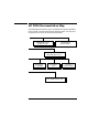
Troubleshooting HP FDDI/9000 Diagnostic Flowcharts Flowchart 2: Configuration Test Figure 4-2 2 A Execute lanscan B C Hardware up ? yes Is your interface displayed ? D Is your system a Series 700 or 800 ? E S800 G Run ioscan H Is driver in kernel ? Is device adapter displayed ? yes RMT: Ring_Op and CF state: WRAP_S ? yes 4 no no yes J 3 Execute: fddistat no F no I 3 Regen kernel with driver K no Check hardware yes L Problem fixed ? no 2 yes Stop 60 Chapter 4
Troubleshooting HP FDDI/9000 Diagnostic Flowcharts Flowchart 2 Procedures NOTE Check that your fiber-optic connectors to the adapter and concentrator (or wall plug) are fully connected before beginning this flowchart. A. Execute: lanscan. Enter the lanscan command to display information about LAN adapters that are successfully bound to the system. For example, enter /etc/lanscan. For more information, see the lanscan manpage. Go to B. B.
Troubleshooting HP FDDI/9000 Diagnostic Flowcharts Class I H/W Path Driver S/W Status H/W Type Description =============================================================== lan 0 48 fddi CLAIMED INTERFACE lan 1 56.1 lan3 CLAIMED INTERFACE H. Class I H/W Path HP J2157A - FDDI Is driver in kernel? If yes, go to J. If no, the driver has not been generated into the kernel and the ioscan -f output will look like the following. Go to I.
Troubleshooting HP FDDI/9000 Diagnostic Flowcharts Flowchart 3: Configuration Test (cont.
Troubleshooting HP FDDI/9000 Diagnostic Flowcharts Flowchart 3 Procedures A. Execute: fddiinit . Reset the adapter and download the adapter firmware by executing fddiinit. For example, if /dev/lan1 is the device file corresponding to your FDDI adapter, enter /usr/sbin/fddiinit /dev/lan1. For Integrated FDDI Model 735, use lan0; for Integrated FDDI Model 755, use lan1. B.
Troubleshooting HP FDDI/9000 Diagnostic Flowcharts Flowchart 4: Configuration Test (cont.) Figure 4-4 4 A Execute ifconfig B Is ifconfig up ? no yes C Execute: ifconfig ...
Troubleshooting HP FDDI/9000 Diagnostic Flowcharts Flowchart 4 Procedures A. Execute: ifconfig . Execute ifconfig without the up parameter on the interface you want to test, to check the flag setting for the up parameter. For example, to check FDDI interface lan1, type: /usr/sbin/ifconfig lan1 B. Is ifconfig up? Check the results of the ifconfig command to see if the interface is up. If it is, go to G. If not, go to C. C. Execute: ifconfig up.
Troubleshooting HP FDDI/9000 Diagnostic Flowcharts Flowchart 5: Configuration Test (cont.
Troubleshooting HP FDDI/9000 Diagnostic Flowcharts Flowchart 5 Procedures A. /usr/sbin/ifconfig not found. The command has been relocated on the system or deleted. Go to E. B. Bad system call; core dumped. Networking is not configured into the HP-UX kernel. Go to F. C. No such interface name. The interface name passed to ifconfig does not exist on the system. Check spelling and names of interfaces on the system using netstat -i.
Troubleshooting HP FDDI/9000 Diagnostic Flowcharts Flowchart 6: Network Level Loopback Test Figure 4-6 6 A Execute: ping to remote host B C ping successful ? yes 8 no Network unreachable ? D yes Local FDDI interface up ? F no E G Command hangs ? Call HP no Configure interface up yes 7 no Unknown host ? I yes yes no No route to host ? yes H Correct BIND, YP or /etc/hosts configuration 6 J Add route table entry no Call HP Chapter 4 69
Troubleshooting HP FDDI/9000 Diagnostic Flowcharts Flowchart 6 Procedures A. Execute: ping to remote host. Using ping(1M), send a message to the remote host you are having problems connecting to. For example: /usr/sbin/ping bunny B. ping successful? If packets are being returned, your system has network level connectivity to the remote host. Note what percentage of the total packets are lost, if any. Losing ten percent or more may indicate the network or remote host is extremely busy.
Troubleshooting HP FDDI/9000 Diagnostic Flowcharts Flowchart 7: Network Level Loopback Test (cont.) Figure 4-7 7 A B no Host entry in ARP cache ? C remote host up ? no D no FDDI adapter ok ? 3 Bring up remote host F no Entry complete ? Replace or reset FDDI adapter yes Call HP E yes yes G Use arp to complete entry 6 yes H ping local host I ping successful ? no Call HP yes 6 Note: This time ping from remote host to local host.
Troubleshooting HP FDDI/9000 Diagnostic Flowcharts Flowchart 7 Procedures A. Host entry in ARP cache? Using arp, check that an entry exists for the remote host in your system's ARP cache. For example: /usr/sbin/arp bunny If the host entry is not in the ARP cache, go to B; otherwise, go to F. B. Remote host up? If yes, go to C. If no, the remote host has not broadcast an ARP message, and that likely is why there is no entry in the ARP cache. Go to E. C. FDDI adapter okay? If yes, call HP.
Troubleshooting HP FDDI/9000 Diagnostic Flowcharts Flowchart 8: Transport Level Loopback Test (using ARPA) Figure 4-8 8 A Execute: telnet to remote host B yes Successful 9 ? C no Execute: ftp to remote host D Successful ? yes Call HP no E TCP configured on local or remote host ? G F no Configure TCP 1 yes Network congested ? Call HP Chapter 4 73
Troubleshooting HP FDDI/9000 Diagnostic Flowcharts Flowchart 8 Procedures A. Execute: telnet to remote host. Try to establish a telnet connection to the remote host. B. Successful? If your telnet attempt was successful, the connection has been made through the Transport Layer (OSI Layer 4). Go to Flowchart 9. C. Execute: ftp to remote host. Unlike telnet, ftp does not go through a pseudoterminal driver (pty) on your system. This step tests to see if the pty is why telnet failed. D.
Troubleshooting HP FDDI/9000 Diagnostic Flowcharts Flowchart 9: Link Level Loopback Test Figure 4-9 9 A Execute: linkloop to remote host B yes linkloop successful ? 10 no C D Loopback FAILED: Address has bad format E Loopback FAILED: Not an individual address F Loopback FAILED G Correct the link address parameter 9 Choose a different remote host; re-execute linkloop H 10 yes linkloop successful ? no I Check remote host connectivity to FDDI 8 Chapter 4 75
Troubleshooting HP FDDI/9000 Diagnostic Flowcharts Flowchart 9 Procedures A. Execute: linkloop to remote host. Enter the link level address (station address) of the remote host in hexadecimal form (preceded by “0x”). Execute lanscan (1M) to find the link level address (station address) on the remote host or obtain it from your network map. B. linkloop successful? If the test was successful, network connectivity is okay through the Link Layer (OSI Layer 2). Go to Flowchart 10.
Troubleshooting HP FDDI/9000 Diagnostic Flowcharts Flowchart 10: Gateway Configuration Test Figure 4-10 10 A Execute: netstat -i B Interface present ? yes no D Re-edit /stand/system C Expected interface ? E yes 11 no Redo ifconfig 4 F Generate new kernel G Shutdown system H Bring up system with new kernel 2 Chapter 4 77
Troubleshooting HP FDDI/9000 Diagnostic Flowcharts Flowchart 10 Procedures A. Execute netstat -i. Check that the network interface exists. At the system prompt, type: netstat -i B. Interface present? Check that the network interface exists. If it does, but with a network interface name you do not expect, go to C to reassign the network interface. If the network interface does not exist, proceed to step D. C.
Troubleshooting HP FDDI/9000 Diagnostic Flowcharts Flowchart 11: Gateway Loopback Test Figure 4-11 11 A Execute: ping from known good host through gateway to known good host C B yes successful ? Check route table on problem host and all hosts between no D Examine gateway E Correct route tables F G Other HP or other vendors, Refer to networking documentation 6 If HP 9000 execute: ifconfig on gateway host H Network interface up ? yes 2 no I Configure interface up 6 Chapter 4 79
Troubleshooting HP FDDI/9000 Diagnostic Flowcharts Flowchart 11 Procedures A. Execute: ping from known good host through gateway to known remote host. This will test gateway connectivity to the remote network. B. Successful? If ping was successful, the problem may exist in the routing table for the problem host. Go to C. If not, go to D. C. Check route table on problem host and all hosts between. Execute netstat -r to examine a route table. Go to E. D. Examine gateway.
Index Symbols /etc/hosts, 49 editing with SAM, 47 /usr/sbin/dmesg, 40 /usr/sbin/route and SAM, 47 A A port, 25, 29 Adapter and MIC connector, 58 configuring, 44 installing, 39 moving, 45 adapter bay, gaining access, 38 Address Resolution Protocol, 72 arp manpage, 14 B B port, 25, 29 BIND name service, 43 C Concentrator, 25, 26, 58 Configuration State (CF_State), 28 Configuring FDDI adapters, 44 gateways, 47 network connectivity, 47 contacting HP, 21 Counter error, 31 frame, 31 receive, 31 transmit, 31 Ind
Index Isolated, 29 K kernel driver status, 62 L LAN adapter configuring, 44 initializing, 44 LAN network interface, powerup, 45 lanscan command, 46 manpage, 14 LEM, see Link Error Monitor, 30 LER Link Error Rate, 30 LER_Estimate Link Error Rate Estimate, 30 Link Error Monitor (LEM), 30 Link Error Rate (LER), 30 Link Error Rate Estimate (LER_Estimate), 30 linkloop, 76 manpage, 14 LLC, see Logical Link Control, 24 Loading software, 36 logging, 16 Logical Link Control (LLC), 24 Loopback tests gateway, 80 link
Index Software configuring with SAM, 44 loading, 36 unloading, 37 static electricity, safeguarding against, 38 Station Management standard, 24 Station Management unit (SMT), 26 Station state, 27 Stations dual-attached, 25 single-attached, 26 System Administration Manager configuring FDDI adapters, 44 configuring network connectivity, 47 description of, 42 domain name format, 43 initializing FDDI adapters, 44 T T_Req Requested Token Rotation Time, 26 Target Token Rotation Time (TTRT), 26 TCP, see Transmissi