
Installing and Administering Internet Services

346 Chapter8
Configuring gated
Configuring the OSPF Protocol
border routers advertise a single route for each address range.
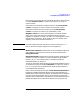
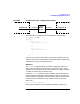
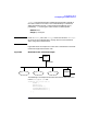
Figure 8-5 shows an example of a router that is connected to area 0.0.0.1
through interface 193.2.1.33. The attached network consists of addresses
193.2.1.33 through 193.2.1.47. The other network in the area consists of
addresses 193.2.1.17 through 193.2.1.31.
Figure 8-5 Network Configuration Example
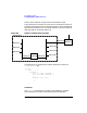
The following is an example of the network definition in Router A’s
/etc/gated.conf file:
ospf yes
area 0.0.0.1
networks {
193.2.1.16 mask 0xfffffff0 ;
193.2.1.32 mask 0xfffffff0 ;
} ;
interface 193.2.1.33 {
...
} ;
} ;
...
Interfaces
The interface statement in the OSPF Protocol definition specifies
which interface to use when communicating with the specified
Router A
193.2.1.33
193.2.1.17
193.2.1.18
193.2.1.19
Area 0.0.0.1
. . .
193.2.1.34
193.2.1.35
. . .
193.2.1.36
Router B
193.2.1.47
193.2.1.31