
HP SVA V2.1 System Administration Guide
When you re-configure a display node's display block, that is, change the layout of tiles in the
display block, the tool automatically updates any Display Surfaces that use that node. For example,
you might choose to re-configure vis3 and vis4 display block layouts to be 1 W x 2 H. The
display_d Display Surface in Table 2-2 would be updated automatically to have a Display
Surface layout of 1 W x 4 H. Note that you would need to change both display blocks to have
the same spatial arrangement. You would need to indicate this at the same time using the Node
Configuration Tool by using multiple node nomenclature, for example, n[3–4]. You cannot
mix display blocks with different spatial arrangements in the same Display Surface.
If you are in the early stages of setting up your displays for your SVA, a recommended process
is as follows:
1. Run the SVA OVP on the set of Display Surfaces defined by the initial configuration of the
cluster. This is likely to be the one created by HP Manufacturing.
2. Use the Node Configuration Tool to configure any individual display nodes that drive
multi-tile output. This process automatically updates any existing Display Surfaces that use
the modified display blocks for the re-configured display nodes.
3. Run the SVA OVP on the same initial set of Display Surfaces, now using the re-configured
display nodes that use multi-tile display blocks.
4. Use the Display Surface Configuration Tool to redefine or create new Display Surfaces using
the multi-tile display blocks from the re-configured display nodes.
5. Run the SVA OVP on the updated set of Display Surfaces.
This incremental configuration and testing process simplifies the assembly, definition, and
verification of your Display Surfaces.
To invoke the Node Configuration Tool, enter the following command:
# svaconfigurenode
You then have four choices:
1. Show Display Block Geometry (any user).
2. Change Display Block Geometry (root users only).
3. Change Render Node to Display Node (root users only).
4. Change Display Node to Render Node (root users only).
To choose an option, enter its number at the Enter request: prompt.
Showing the existing display block geometry for specified nodes is straightforward. After entering
the Show Display Block Geometry option, enter the node names for which you want
information, for example:
tigger[25-32]
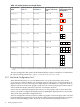
The tool provides output such as the following:
Width Height Nodes
1 1 tigger[25-32]
2.3.1.1 Change Node Type
This tool also lets you change render nodes to and from display nodes. Using the same options
listed in Section 2.3.1, choose the appropriate option (3 or 4) to change the role of a node. You'll
then be prompted to enter the name of the node whose role you want to change. Note that you
may need to reboot any display nodes that had previously been render nodes.
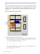
To change the display block geometry for one or more nodes, choose the appropriate option.
You are then prompted for one or more display nodes. All nodes that you enter will be
re-configured to have the same display block geometry. Finally, you are prompted for the relative
orientation of the tiles that make up a display block, that is the width and height of the display
2.3 Configure Display Nodes and Display Surfaces 33