
HP SVA V2.1 System Administration Guide
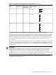
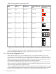
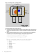
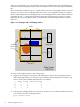
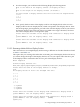

Table 2-2 Display Surfaces in a Sample Cluster
Display Surface Layout
Showing Display Blocks,
Including Tiles
1
Resulting Display Surface
Layout in Terms of Tile
Units
Display Block Layout
from Table 2-1
Display Nodes from
Table 2-1
Display Surface
Name
1 W x 1 H1 W x 1 H
vis1display_a
2 W x 1 H1 W x 1 H
vis1, vis2display_b
1 W x 2 H1 W x 1 H
vis1, vis2display_c
2 W x 2 H2 W x 1 H
vis3, vis4display_d
4 W x 1 H2 W x 1 H
vis3, vis4display_e
4 W x 2 H2 W x 2 H
vis5, vis6display_f
2 W 4 H1 W x 4 H
vis7, vis8display_g
1 Display surface outlined in red; display blocks outlined in solid black; tiles within display blocks separated by dashed
line.
The Site Configuration File retains all the defined Display Surfaces available for a visualization
job. The Site Configuration File is /hptc_cluster/sva/etc/sva.conf.
2.3.1 Use Node Configuration Tool
When HP Manufacturing or your site administrator sets up the SVA initially, they run the
svaconfigure Utility to define a set of Display Surfaces. This process creates an initial set of
Display Surfaces, each of which maps to a single display node and drives a single tile. Even if a
display node has more than one graphics card, only one card and a single port on that card are
used to define the Display Surface for this base set of Display Surfaces.
If your SVA uses individual display nodes with one or two graphics cards to drive more than
one tile, you need to configure the display nodes by defining the display blocks for those nodes.
This is done using the Node Configuration Tool.
The SVA configuration already stores the number of graphics cards in a display node. You need
to use the Node Configuration Tool to specify the number and orientation of the tiles in a display
block for individual display nodes. This is the sort of information presented in Table 2-1.
32 Setting Up Display Devices