
HP SVA V2.1 System Administration Guide
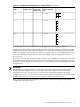
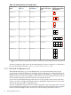
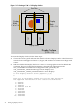
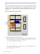
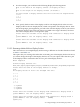
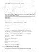

Table 2-1 Display Block Configurations in a Sample Cluster (continued)
Display Block Layout Showing Tiles
1
Display Block Layout
Based on Single Tile
Units
Number of Ports
Used for Each
Graphics Card
Number of
Graphics Cards
Display Node
Name
2 W x 2 H22
vis6
1 W x 4 H22
vis7
1 W x 4 H22
vis8
1 Display blocks are outlined in solid black; tiles within display blocks are separated by a dashed line.
Applications display images using a Display Surface. A Display Surface is defined by specific
display blocks (as represented by both display nodes and associated display devices) and the
spatial arrangement of the display blocks that you specify when you create the Display Surface.
You create and define Display Surfaces using the Display Surface Configuration Tool (see
Section 2.3.2).
Once you create and define a named Display Surface, it is available for use whenever you launch
a visualization job. Because the cluster can have several display block configurations, you can
define one or more Display Surfaces based on how you choose to use the available display block
configurations.
IMPORTANT:
When defining a Display Surface, you must use only display blocks with the same spatial
arrangement. For example, display_b in Table 2-2 has two display blocks both with a
configuration of 1 W x 1 H. display_f in Table 2-2 has two display blocks both with a
configuration of 2 W x 2 H. It does not matter how the spatial arrangement is generated by the
display nodes; that is, by using one or two graphics cards, or one or two ports.
Table 2-2 lists some (but not all) Display Surfaces that can be built using the display block
configurations listed in Table 2-1.
2.3 Configure Display Nodes and Display Surfaces 31