HP Scalable Visualization Array Version 1.
© Copyright 2005, 2006 Hewlett-Packard Development Company, L.P. Confidential computer software. Valid license from HP required for possession, use or copying. Consistent with FAR 12.211 and 12.212, Commercial Computer Software, Computer Software Documentation, and Technical Data for Commercial Items are licensed to the U.S. Government under vendor's standard commercial license. The information contained herein is subject to change without notice.
Table of Contents About This Document.....................................................................................9 Intended Audience..................................................................................................................................9 Document Organization...........................................................................................................................9 Typographic Conventions......................................................................
Error Reporting................................................................................................................................40 Example.........................................................................................................................................40 svaverify(8)..........................................................................................................................................40 Options...........................................................
List of Figures 1-1 1-2 1-3 1-4 1-5 Cabling Reference: Graphic Card Ports..................................................................................................23 Cabling Reference for Multi-Tile Display Blocks: Two Cards........................................................................23 Cabling Reference for Multi-Tile Display Blocks: One Card........................................................................23 Creating a 2 W x 1 H Display Surface....................................
List of Tables 1-1 1-2 1-3 1-4 1-5 1-6 1-7 1-8 1-9 Site Configuration File: Tag Definitions for the SVA_JOB Section.................................................................16 Site Configuration File: Section/Tag Definitions........................................................................................17 Site Configuration File: Section/Tag Definitions (cont.)..............................................................................17 Site Configuration File: Section/Tag Definitions....
About This Document This document describes system administration tasks that are specific to the SVA. Intended Audience Primary: System administrators; secondary: application developers. Document Organization This document is organized as follows: Chapter 1 Use this chapter to learn about the data configuration files; how to set up Display Surfaces, display nodes, and display devices; and licensing.
Related Information Related documentation is available via links from the home page for the SVA Documentation Library. It also includes links to third party documentation available on the Web that is relevant to users of SVA. Publishing History The document printing date and part number indicate the document’s current edition. The printing date will change when a new edition is printed. Minor changes may be made at reprint without changing the printing date.
1 SVA System Administration Tasks This chapter describes tasks system administrators commonly do on the Scalable Visualization Array (SVA). Many of the tasks described in this chapter typically require root privileges and knowledge of the hardware components of the SVA and its software configuration. Configuration Data Files This section describes the general format and content of the Configuration Data Files: • Site Configuration File. • User Configuration File. • Job Settings File.
Tag Names Tag names represent general characteristics of the SVA that are needed or useful for allocating resources, launching jobs, and managing the way jobs execute. Tags names have the following characteristics: • Tag names are case sensitive. • Tag names must begin in column one. • Tag names cannot include spaces or special characters. • The tag name and equal sign cannot have any space between them. Tag names equate with tag values. See “Section and Tag Contents” (pg. 12) for examples.
1. 2. 3. 4. Command line options. The Job Settings File. The User Configuration File. The Site Configuration File. Site Configuration File The Site Configuration File contains default system settings. It is located on the head node at /opt/sva/etc/sva.conf. HP generates the file automatically using the svaconfigure utility after the cluster operating system software is installed. Use the svaconfigure utility to add or remove a node from the cluster. See “Changing Data Files” (pg. 20) for more information.
# Declare a display surface [SVA_DS_1_2] SVA_RENDER_HOSTS="red[3-4]" SVA_EXECUTION_HOST="red2" SVA_DISPLAY_HOSTS="red2" red2.COORDINATE="0.0" # Declare a display surface [RED1] SVA_RENDER_HOSTS="" SVA_EXECUTION_HOST="red1" SVA_DISPLAY_HOSTS="red1" red1.COORDINATE="0.0" # Declare a display surface [RED2] SVA_RENDER_HOSTS="" SVA_EXECUTION_HOST="red2" SVA_DISPLAY_HOSTS="red2" red2.COORDINATE="0.0" See “Changing Data Files” (pg. 20) for a description of how to change the Site Configuration File.
# Declare job resource counts [SVA_JOB] SVA_DISPLAY_SURFACE=surface_name SVA_EXECUTION_HOST=host_name SVA_EXTERNAL_HOST=FQDN SVA_RENDER_COUNT=n SVA_RENDER_HOSTS=host_names SVA_COMPUTE_COUNT=n SVA_COMPUTE_HOSTS=host_names SVA_DISPLAY_COUNT=n SVA_DISPLAY_HOSTS=host_names SVA_USE_REMOTE3D=boolean SVA_USE_DMX=boolean SVA_DMX_STARTUP=host_name SVA_DMX_INPUT=host_name SVA_SEPIA_HOSTS=host_names SVA_PARTITION=partition_name # Declare job-specific information # for each host in the job [host_name] SVA_ROLE=role SVA
Table 1-1 Site Configuration File: Tag Definitions for the SVA_JOB Section Tag within Section Definition SVA_JOB Declare site default settings for all jobs. All the tags in SVA_JOB can be superseded by values in the User Configuration File. SVA_USE_REMOTE3D Indicates whether or not HP Remote Graphics Software is used by default for all jobs. SVA_USE_DMX Indicates whether or not DMX is used by default for all jobs. SVA_PARTITION The name of the SLURM partition from which to request resources.
Table 1-2 Site Configuration File: Section/Tag Definitions Section Tag within Section Definition [SVA_CLUSTER] SVA_CLUSTER_NAME The name of the cluster. This can be set by the site administrator using the svaconfigure utility. It defaults to the external node name of the head node. Defines default site settings for the session. This section appears in the Site Configuration File only. Identifies cluster-specific user configuration files when using svagetdata calls.
Table 1-4 Site Configuration File: Section/Tag Definitions INSTANCE [host_name] Tags within INSTANCE 1 SVA_ROLE Each display and render host is listed. The role of the host; that is, render or display. For this tag and section, the value is always set to DISPLAY. For each display node, it is listed with its specific role, tile number, orientation, and external name. SVA_NUM_TILES1 For each render node with external NICs, it is listed with its specific role and external Display nodes only. name.
Table 1-5 User Configuration File: Tag Definitions for the SVA_JOB Section Tags within Section Definition SVA_JOB Declares default settings for all jobs. SVA_ALLOCATOR_OPTIONS Provides a means to supply options to the SVA job allocator. These options affect its choice of nodes. More than one option can be used by separating the options with a space.
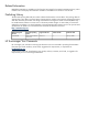
Job Settings Configuration Section and Tag Entries Table 1-6 and Table 1-7 define sections and their associated tags in the Job Settings File. Table 1-6 Job Configuration File: Tag Definitions for the SVA_JOB Section Tags within Section Definition SVA_JOB Declares site default settings for all jobs. SVA_DISPLAY_COUNT The number of display nodes assigned to a job. SVA_RENDER_COUNT1 The number of render nodes assigned to a job. 1 SVA_COMPUTE_COUNT The number of compute nodes assigned to a job.
See “Configuring Display Nodes and Display Surfaces” (pg. 23) for information on how to create new Display Surfaces in the Site Configuration File for your cluster environment, including multi-tile Display Surfaces. The Site Configuration File is called /opt/sva/etc/sva.conf. Once this Site Configuration File is created, you can customize it to your site needs.
Working with Displays You must carry out several tasks to display images correctly on display devices using SVA: • Physically setting up display nodes and display devices. Plan how you want the display devices arranged, and how you want to use your display nodes to drive your display devices. It also involves cabling the display nodes to the display devices. • Defining Display Surfaces.
Figure 1-1 Cabling Reference: Graphic Card Ports Cable to flat panel Cable to flat panel A B 1 2 7 6 5 4 3 2 1 Figure 1-2 Cabling Reference for Multi-Tile Display Blocks: Two Cards A,2 A,1 B,2 B,1 A,2 B,2 A,2 B,2 B,1 A,2 A,1 A,2 A,2 A,2 A,1 B,2 B,2 B,2 B,1 B,2 B,1 B,1 Figure 1-3 Cabling Reference for Multi-Tile Display Blocks: One Card A,2 A,2 A,2 A,1 A,1 Configuring Display Nodes and Display Surfaces To understand the way the SVA uses Display Surfaces, you must understand the
Surface, you must provide the correct host name of the display node connected to the display device that is associated with each display block that makes up that Display Surface. • Use both outputs from a graphics card to drive two display devices. In this situation, graphics cards and display devices exist in a 1:2 relationship. The display node's graphics card and the two display devices are physically connected by cables.
display blocks that you specify when you create the Display Surface. You create and define Display Surfaces using the Display Surface Configuration Tool. See "Using the Display Surface Configuration Tool" . Once you create and define a named Display Surface, it is available for use whenever you launch a visualization job. Because your cluster can have several display block configurations, you can define one or more Display Surfaces based on how you choose to use the available display block configurations.
Use Node Configuration Tool When HP Manufacturing or your site administrator set up the SVA initially, they run the svaconfigure Utility to define a set of Display Surfaces. This process creates an initial set of Display Surfaces, each of which maps to a single display node and drives a single tile. Even if a display node has more than one graphics card, only one card is used to define the Display Surface for this base set of Display Surfaces.
warning if your re-configured display blocks might result in a Display Surface made up of display blocks with different geometries. If you proceed, the inconsistent Display Surfaces are deleted. Using the Display Surface Configuration Tool The initial generation of the Site Configuration File cannot automatically specify all the necessary Display Surfaces, because Display Surfaces are site-specific and can change.
For example, assume you want to create a Display Surface like display_b listed in Table 1-9 using the available display blocks also listed in Table 1-9. This is a Display Surface with display blocks assembled to create a 2 W x 1 H Display Surface configuration with the second display block oriented to the right of the first display block as shown in Figure 1-4. Each of the two display blocks has a 1 W x 1 H configuration; that is, maps to a single display device (tile).
1 You have chosen a display surface that will look like the diagram below: +----+----+ | 1 | 2 | +----+----+ Note If you're an application developer, bear in mind that the lower left corner of the Display Surface is regarded as the origin. Therefore, the lower left corner of tile 1 corresponds to (0,0). The image subcomponents are ordered from that point, left to right and then bottom to top.
Figure 1-5 Creating a 2 W x 2 H Display Surface File Vis4 Two Tiles View Display Nodes Vis3 Two Display Blocks: 2 W x1H Two Tiles Display Surface (2 W x 2 H) To create such a Display Surface, follow these steps: 1. Begin by choosing the Create option and entering the name for the new Display Surface. At this point, you will see a list of the available display blocks, for example: 1) 2) 3) 4) 2.
Return, provides a list of all the display nodes in your cluster. For Display Surfaces, the lower left corner is regarded as the origin. Therefore, the lower left corner of display block 1 corresponds to (0,0).
Once you replace a node, you can use the replaced node to take the place of another node in the Display Surface.
DoubleTall,TripleWide Choose the Display Surfaces to change from the previous list. Place all names on a single line, separated by spaces or commas.
• Copy the data files to the head node as in the previous option. Use the Administrative Network (GigE) rather than the SI to share the data files to all other nodes. This option is useful if the application loads the SI, for example; with MPI traffic. • Access the data files stored on an external file system such as HP SFS. You can access the data directly from the visualization nodes using GigE NICs in the nodes. It is also possible to make use of the SI for the data traffic.
# service sva-lm restart Configuring HP Remote Graphics Software (RGS) RGS is an optional package that you can use to display images created on the SVA on a display device that is remote to the cluster. RGS requires some additional configuration and installation steps that are not documented in the RGS installation instructions. Refer to the SVA Software Installation Guide for details.
2 Diagnostic Commands This chapter describes the SVA diagnostic utilities. The following standard terminology is used in the Description section for each command: • Users: Users of the diagnostic command. • Runs On: The type of nodes on which the diagnostic runs, specifically, administrative node or cluster nodes. • Mode: The type of system access the command requires. Non-exclusive access means that a diagnostic can run even if other utilities are using the subsystem being tested.
sva_ovp(8) sva_ovp sva_ovp -- Verifies that the components of an SVA system are working properly. Synopsis sva_ovp { -d display-surface,... } [ -g geometry ,...] [ -i display ] [ -l ] [ -h ] Options -d display-surface or --display-surface name -g geometry or --tile_geometry geometry -i display or --input_display display -l or --long-runtime -h or --help Specifies the list of Display Surfaces to test. It defaults to the first supported display resolution.
• ERROR: Test and Ref files are different.(w/X.X dB of noise) This means that although the image was generated, it was considered different than the reference image. • ERROR: Reference file (%s) doesn't exist This means that the OVP doesn't have a reference file matching your Display Surface's resolution. The test may have run correctly; but the OVP doesn't have a way of verifying the results.
svaverify(8) svaverify svaverify -- Verifies that the Site Configuration Data File is valid. Synopsis svaverify [ -v ] [ -V ] [ -h ] Options -v or --verbose -V or --Version -h or --help Displays readable output of the allocation process. Used for debugging only. Displays the version number of this program. Prints usage information. Description Users Runs On Mode Subsystems Tested Supply Chain, Delivery, Field Service, System Administrator. Head node. Non-exclusive. • Directly: Site Configuration File.
Glossary Administrative Network bounded configuration Chromium compute node Configuration Data Files display node display block Display Surface Display Surface Configuration Tool Connects all nodes in the cluster. In an HP XC compute cluster, this consists of two branches: the Administrative Network and the Console Network. This private local Ethernet network runs TCP/IP. The Administrative Network is Gigabit Ethernet (GigE); the Console Network is 10/100 BaseT.
DMX interactive session Job Settings File LSF Node Configuration Tool ParaView Remote Graphics Software (HP) render node Site Configuration File SLURM svaconfigure Utility System Interconnect 42 Glossary arrangement of the display blocks. Invoked using the svadisplaysurface command. Requires root privileges. Distributed Multi-Head X is a proxy X Server that provides multi-head support for multiple displays attached to different machines (each of which is running a typical X Server).
tile UBB UVB VBB Myrinet can be used for the System Interconnect to speed the transfer of image data and drawing commands to the visualization nodes. The image output from the a single port of a graphics card in a display node. Typically, a tile is also considered the image displayed on a single display device such as a flat panel or projector. Utility Building Block (UBB). Base utility unit of a modular expandable SVA system.
Index C S Configuration data files changes to, 20 check syntax for, 33 general format of, 11 hierarchy of, 12 include statement within, 12 Section and Tag definitions, 15 Configuration File Checker, 33, 40 SFS use to access data, 33 Site configuration file, 11 generated initially using svaconfigure utility, 20 verifying, 40 svaconfigure utility used for Site Configuration File, 21 svaverify, 40 D Data file access, 33 Diagnostic commands Configuration File Checker, 40 SVA OVP, 38 Display block defined, 2