Printing History 1997 by Storage Technology Corporation and Hewlett-Packard Company. All rights reserved.
Hardware Operator’s Guide List of Pages Document Title: Manufacturing Document PN: Customer Document PN: Vendor PN: Edition 1 A4853A Hardware Operator’s Guide A4853–96000 A4853–90000 95770 1 November 1997 EC# 83907 This guide has 62 pages. Page Change No.
Hardware Operator’s Guide This page intentionally left blank.
Hardware Operator’s Guide Contents About This Guide . . . . . . . . . . . . . . . . . . . . . . . . . . . . . . . . . . . . . . . . . . . . . . . . . vii Chapter 1. Getting Started . . . . . . . . . . . . . . . . . . . . . . . . . . . . . . . . . . . . . . . . . 1–1 Library Components . . . . . . . . . . . . . . . . . . . . . . . . . . . . . . . . . . . . . . . . . . . . . . . . . . . . . . . . . . . . . Robot Assembly . . . . . . . . . . . . . . . . . . . . . . . . . . . . . . . . . . . . . . . . . .
Hardware Operator’s Guide Illustrations Figure 1–1. Figure 1–2. Figure 1–3. Figure 1–4. Figure 2–1. Figure 2–2. Figure 3–1. Figure 3–2. Figure 3–3. Figure 3–4. Figure 3–5. Figure 3–6. Figure 3–7. Figure 3–8. Figure 3–9. Figure 4–1. Figure 4–2. Figure 4–3. Library Front View . . . . . . . . . . . . . . . . . . . . . . . . . . . . . . . . . . . . . . . . . . . . . . . . . . . . A4853A Library Major Components . . . . . . . . . . . . . . . . . . . . . . . . . . . . . . . . . . . . . .
Organization Hardware Operator’s Guide About This Guide This guide explains the operation of the Digital Linear Tape (DLT) Library for the person in charge of monitoring its day-to-day operation. Organization This guide is organized as follows: Chapter 1 “Getting Started” explains the basic configuration of the DLT Library, its features and major components, powering on, and the library startup routine.
Related Publications Hardware Operator’s Guide WARNING A warning calls attention to a procedure or practice that could result in personal injury if not correctly performed. Do not proceed beyond this warning until you fully understand and meet the indicated conditions. Related Publications Additional information is contained in the manuals that accompany your tape drives. Conventions A sans–serif font is used in this manual to denote function buttons such as ENTER, MENU, or SYSTEM RESET.
Internal Code License Statement Hardware Operator’s Guide Internal Code License Statement DLT Library ix
Internal Code License Statement x Hardware Operator’s Guide DLT Library
Regulatory Statements Hardware Operator’s Guide Regulatory Statements FCC Radio Frequency Interference Statement (USA) Note: This equipment generates, uses and can radiate radio frequency energy. If it is not installed and used in accordance with the instruction manual, it may cause interference to radio communications.
Regulatory Statements Hardware Operator’s Guide General Approval (U.K.) Note: The Hewlett-Packard A4853A DLT Library is approved under approval number NS/G/1234/J/100003 for indirect connection to Public Telecommunication Systems in the U.K. VCCI Class A (Japan) Note: This equipment is in the Class A category information technology equipment based on the rules of Voluntary Control Council For Interference by Information Technology Equipment (VCCI).
Hardware Operator’s Guide Declaration of Conformity Declaration of Conformity DLT Library xiii
Declaration of Conformity Hardware Operator’s Guide This page intentionally left blank.
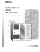
Chapter 1. Getting Started The Digital Linear Tape (DLT) Library is a self-contained, rack-mountable, fully automated cartridge system that can accommodate three tape drives and 30 cartridges. The library uses a small computer system interface (SCSI) library command set and attaches directly to the SCSI bus. Figure 1–1.
Library Components Hardware Operator’s Guide Library Components The major components of the library, as shown in Figure 1–2, are S S S S S S Figure 1–2.
Hardware Operator’s Guide Library Components Robot Assembly The robot moves cartridges to and from the storage cells, the CAP, and the tape drives when directed by the host (controlling) software. The robot’s major components are a Z column assembly and a hand/camera assembly. A theta motor and Z motor enable horizontal and vertical motion, respectively. Z Column Assembly The Z column assembly incorporates the mechanisms necessary to move the hand vertically and in horizontal rotation (theta).
Library Components Hardware Operator’s Guide Storage Cells The DLT Library contains storage cells for 30 DLT type IV or type IIIXT cartridge tapes. Figure 1–3 shows the cell locations. If Auto Clean is enabled, column 0, cell 7 cannot be used for a data cartridge, because a cleaning cartridge must be placed in that cell. Auto Clean is discussed in Chapter 3 of this guide. Figure 1–3. Storage Cell Locations In this figure, the number in parentheses equals the total cartridge count.
Hardware Operator’s Guide DLT Library Safety Features Operator Panel The library operator panel includes a display for viewing library and tape drive status. The operator panel also includes five function buttons and three LEDs. The function buttons allow access to all of the menus, status displays, machine diagnostics, and error information available for the library. DLT Library Safety Features The DLT Library features a safety interlock that shuts off power to the robot if the front door is opened.
Powering On the Library Hardware Operator’s Guide Powering On the Library The library power switch is located on the upper right rear of the unit, as shown in Figure 1–4, below. When the DLT Library is powered on or reset, it performs a complete diagnostic routine and a tape audit. If the front door is opened and closed while power is on, the library performs a tape audit only. During these operations, the library displays its current activity on the display panel. Figure 1–4.
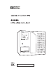
Chapter 2. Operating the Library The Digital Linear Tape (DLT) Library operator panel includes a four-line, 20-character per line, backlit display for viewing library and tape drive status. The operator panel also includes five function buttons and three light-emitting diodes (LEDs). The function buttons allow access to all of the menus, status displays, machine diagnostics, and error information available for the DLT Library. Figure 2–1 shows the operator panel with a typical Status Display visible.
Operator Panel Controls Hardware Operator’s Guide Operator Panel Controls The operator panel has five function buttons. MENU The MENU button toggles the display between the Main Menu and Library/Drive Status. The MENU button calls up the previous (higher) level menu if the library displays one of the nested menus. ENTER The ENTER button has two functions: — It selects the option indicated by the menu cursor (>). — It opens the cartridge access port (CAP) when that is enabled.
Menus and Displays Hardware Operator’s Guide Menus and Displays The hierarchy of menus and status displays in the DLT Library is shown in Figure 2–2. Figure 2–2. Operator Panel Menu Flow Chart To select an item, move the cursor using the up or down arrows until it points to the item, and press ENTER. To return to a higher level menu, press MENU. Main Menu > Status Display Library Utilities Drive Utilities DLT Library Status Display Shows the current library and DLT drive status.
Main Menu Hardware Operator’s Guide Status Display The first line of the status display (the library status line) shows the state of the CAP. The normal CAP states are CAP Locked, No Entry The cartridge access port cannot be used. ENTER Unlocks CAP The cartridge access port can be unlocked by pressing the ENTER key. CAP Unlocked The cartridge access port is ready to be opened.
Main Menu Hardware Operator’s Guide Library Utilities The Library Utilities menu displays diagnostic, error, and configuration options. > Library Diags Examine FSCs View Configuration Set Configuration Library Diags Accesses diagnostic routines for the library. Examine FSCs Displays the last 20 fault symptom codes. View Configuration Displays the current library configuration. Set Configuration Accesses library configuration options.
Main Menu Hardware Operator’s Guide When you first choose a diagnostic option, the library prompts you to press ENTER to put the library in Maintenance Mode. Note: In Maintenance Mode, the library goes offline to the host. Make sure all host activity has stopped before proceeding. If you wish to continue, the display prompts you to insert a “diagnostic” cartridge. A diagnostic cartridge is an ordinary type IV or type IIIXT cartridge with a “DG” label attached.
Main Menu Hardware Operator’s Guide View Configuration View Configuration shows the library/drive configuration, as in the example below. Code Vers: x.x.xx SCSI ID = 0 3 Drives Installed Fast Load – ON Auto Clean – OFF Drv 2 NOT Configed Drv 1 SCSI ID – 0 Drv 0 SCSI ID – 0 The operator panel displays only four lines. Use the arrow buttons to scroll through the options. Set Configuration Set Configuration displays library and drive configuration options.
Main Menu Hardware Operator’s Guide Drive Utilities Drive Utilities displays tape drive utility options. > Clean a Drive Change Clean Cart Enter Clean Limit Uncal Drive Target Clean a Drive Allows the operator to manually insert a cleaning cartridge through the CAP and specify the drive to be cleaned. Change Clean Cart When Auto Clean is enabled, allows the operator to change the cleaning cartridge residing in the library.
Chapter 3. Maintaining the Library This chapter describes various Digital Linear Tape (DLT) Library manual operations that might be necessary from time to time, such as using the cartridge access port (CAP) and cleaning tape drives. Inserting a Cartridge into the CAP While the library is operating in automated mode, the robot mounts and dismounts cartridges to the tape drives automatically on request from the host software.
Removing a Cartridge from the CAP Hardware Operator’s Guide Removing a Cartridge from the CAP After the robot has placed a cartridge in the CAP, press ENTER to unlock the CAP door. Open the door, remove the cartridge, and close the door. Note: A small lip in the CAP slot prevents cartridges from slipping out of place. When removing a cartridge, lift it slightly to clear the lip.
Hardware Operator’s Guide Manual Operations If the library robot becomes inoperative and you want to mount a tape into a drive, the hand/camera assembly might be in the way of the cartridge tape you want to reach, whether that tape is in a tape drive or a storage cell. To move the hand/camera assembly to reach a cartridge or drive 1. Unlock and open the front door. (Power to the robot is disconnected, although the tape drives will still be powered on and operable.) 2.
Manual Operations Hardware Operator’s Guide CAUTION: Make sure the picker assembly, shown in Figure 3–3, is retracted before moving the hand, to prevent it from striking the storage cells. Push it back with your finger. Figure 3–3. Retracting the Picker Assembly Removing a Cartridge from the Hand If the library becomes inoperative with a cartridge in the hand, you can remove the cartridge using the following procedure: 1. Rotate the robot/hand until it is aligned with the CAP or any empty storage cell.
Hardware Operator’s Guide Figure 3–4.
Manual Operations Hardware Operator’s Guide Removing/Replacing a Cartridge in the Storage Cells Figure 3–5 shows the storage cell locations in the library, arranged in columns. When you locate the cartridge tape you need, pull it straight out of the cell. Figure 3–5. Storage Cell Locations In this figure, the number in parentheses equals the total cartridge count. The other number is the storage cell number in one of the three columns. The storage cell layout as a whole is called the “array.
Hardware Operator’s Guide Figure 3–6. Manual Operations Removing/Replacing a Cartridge Tape in a Storage Cell When manually placing cartridge tapes in storage cells, replace the cartridge right side up (writing on top) with the VOLSER label facing out, as shown in Figure 3–6. Mounting a Cartridge into a Drive To manually mount a cartridge tape into a tape drive, the load latch must be up, which indicates the drive is open.
Manual Operations Figure 3–7.
Hardware Operator’s Guide Figure 3–8. Manual Operations Mounting a Cartridge into a Drive To mount a cartridge into a drive (shown in Figure 3–8 removed from the library for clarity) 1. With the drive open (load latch up), insert the cartridge right side up (writing on top) with the VOLSER label facing out. 2. Push the cartridge fully into the drive until the drive latches onto the tape. 3. Lower the load latch. Dismounting a Cartridge from a Drive To dismount a cartridge from a drive 1.
Manual Operations Hardware Operator’s Guide Tape Drive LEDs The right side LEDs on the tape drive face are shown in Figure 3–9 and explained in Table 3–1. Figure 3–9.
Manual Operations Hardware Operator’s Guide Table 3–1.
Manual Operations Hardware Operator’s Guide This page intentionally left blank.
Chapter 4. Handling Cartridge Tapes Generally observe the following protocols when handling cartridge tapes: S S S S S S S Keep cartridges clean. Inspect cartridges before each use. Never put a damaged cartridge into a drive or storage cell. Do not open cartridges or release the cartridge latch and pull out tape. Do not handle tape that is outside the cartridge. Do not expose the tape or cartridge to direct sunlight or moisture. Do not expose a recorded cartridge to magnetic fields.
Applying Cartridge Labels Hardware Operator’s Guide Applying Cartridge Labels The DLT Library uses type IV or type IIIXT cartridge tapes for data, plus diagnostic and cleaning cartridges. Different types of data cartridge are distinguished by a small letter next to the last number in the VOLSER. Cleaning and diagnostic cartridges are distinguished by a two or three letter prefix in the VOLSER. The correct labeling is as follows: S S S S Type IV data cartridges should be labeled with a “D” label.
Hardware Operator’s Guide Setting Cartridge Write Protection Setting Cartridge Write Protection Refer to Figure 4–3 to see the location of the write protect switch. To set the cartridge to write protected, slide the switch to the left so the orange indicator is visible. In this position, the drive can only read data from the tape and cannot write data to the tape. To set the cartridge to write enabled, slide the switch to the right so the orange indicator is not visible.
Cleaning the Cartridge Exterior Hardware Operator’s Guide Cleaning the Cartridge Exterior Wipe all dust, dirt, and moisture from the cartridge with a lint-free cloth. CAUTION: To prevent tape damage, do not use acetone, trichloroethane, toluene, xylene, benzene, ketone, methylethyl ketone, methylene chloride, ethyldichloride, esters, ethyl acetate, or similar chemicals to clean cartridges.
Appendix A. Specifications This appendix includes numbers for DLT Library supplies and accessories, instructions for ordering cartridge tape labels, and equipment specifications. Supplies and Accessories Table A–1.
Supplies and Accessories Item Hardware Operator’s Guide HP Product Number HP Part Number SCSI Cables for V–Class (68–pin to 68–pin) 5.0m SCSI cable High-density with thumb screws to high-density with thumb screws, m–m with inline terminator for V–Class Not applicable A4801–63004 10m SCSI cable High-density with thumb screws to high-density with thumb screws, m–m with inline terminator for V-Class Not applicable A4801–63002 1.
Supplies and Accessories Hardware Operator’s Guide Acquiring Additional Labels Each DLT Library is supplied with a sufficient quantity of type IV data cartridge labels (with the “D” designation) to match a fully populated library (30 cartridges). To order additional lables, contact Engineered Data Products (EDP) for a reference to a dealer who services your area. Engineered Data Products, Inc. (EDP) 2550 West Midway Blvd. Broomfield, CO 80020 U.S.
Supplies and Accessories Hardware Operator’s Guide DLT Library Specifications Tables A–3 through A–6 provide A4853A DLT Library specifications. Table A–3.
Supplies and Accessories Hardware Operator’s Guide Table A–5. Power Specifications Item Measurement Input Voltage 90–264 VAC, single phase Frequency 47–63 Hz Maximum power consumption (library) 1.0 A at 120 V or 0.5 A at 240 V Table A–6.
Supplies and Accessories Hardware Operator’s Guide This page intentionally left blank.
Glossary A E Ampere. " ! # A field replaceable unit of Alternating Current. the library incorporating the library controller card (CYC), fan assemblies, and power supply. American National Standards Institute. American Standard Code for Information Interchange. # " An operation performed by the DLT Library to track VOLSERs and cartridge locations.
Hardware Operator’s Guide ! !' # # " $ The library menu offering library utility selections. # The mechanism used by the library robot to open and close tape drives for mounting and dismounting cartridge tapes. S " #' # ! "& # A switch that disconnects power to the library when the front door is opened. Small Computer System Interface. % A host adapter or control unit M attached to the SCSI bus. Meter. offering library and drive configuration selections.
Index $"* 4 "-/&#& /&+*. ,,(4&*$ -/-&!$" ( "(. --+2 0//+*. 0/+ (" * !". -&,/&+* "* (&*$ +*#&$0- /&+* ."//&*$ 1&"2 +*/-+((&*$ %+./ .+#/2 -" -! ! /" *! /&)" ."//&*$ !")+ )+!" -/-&!$" ".. ,+-/ ./ /". !& $*+./& . !")+ )+!" !&.)+0*/ -/-&!$" $"/ ,0/ (++, &*&/& (&5" )" % *& (. )+0*/ -/-&!$" )+0*/ !&.)+0*/ (++, 0*(+ ' -/-&!$" ( "(. ,,(4&*$ !&.)+0*/&*$ -/-&!$". #-+) !-&1".
Hardware Operator’s Guide G "+).( $(" 1 H &$ + +2 ' (., &$ + +2 )* + -)+ * ( & &$ + +2 ,- -., /$ 0$(" M # ( ' + ,, ' &2 ')/$(" + ')/$(" +-+$ " , !+)' ' $( ' (. # ( &$(" +-+$ " - * , ' (. & )* + -$)(, #),- )(-+)&&$(" ,)!-0 + .--)( ' $(- $($(" &$ + +2 ' (. !&)0 # +- I ' (. $- ', , & -$(" ' ,, " , &$ + +2 ,- -., $(, +-$(" +-+$ " $( ').
Hardware Operator’s Guide * &(. * )% *,*# ! + * &(.#'! *,*# ! *(& * &(.#'! *,*# ! *(& " ' -,,(' * ,* ,#'! ," *,*# ! )# $ * *( (, ++ & %1 " ' & * ," , &(,(* (%-&' &(,(* S + ,1 ,-* + %# * *1 &-% ,#(' &( + ,,#'! *#. %# * *1 + *.# 0 +) # # ,#('+ ! ' 1 *,# # ,#('+ '.
Hardware Operator’s Guide This page intentionally left blank.
Reader Comment Sheet A4853A DLT Library: Hardware Operator’s Guide We welcome your evaluation of this manual. Your comments and suggestions will help us improve our publications. Remove this page and mail or FAX it to 916–785–2875. Use and attach additional pages if necessary. Agree Disagree N/A The manual is well organized. The information is technically accurate. Information is easy to find. Step–by–step procedures are easy to perform. There are enough examples and pictures.