
HP SureStore E Disk Array FC60 Service Manual (A5635A)

354 Internal Controller Enclosure Assemblies
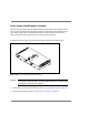
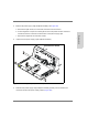
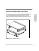
6. Slide the power supply cage/ midplane assembly all the way into the chassis and install
the eight screws (four each side). See Figure 123.
7. Install the controller enclosure into the rack (reverse the procedure "Controller
Enclosure" on page 342).
Battery Harness
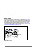
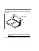
The controller module contains one battery harness. The battery harness (Figure 124) is a
ribbon cable that provides a power connection between the Battery Backup (BBU) module
and the controller enclosure midplane. The harness also carries battery status information.
Removal and replacement of the battery harnesses is described as part of the controller
cage/ midplane assembly procedure. To replace the battery harnesses, refer to "Controller
Cage/ Midplane Assembly / Battery Harness" on page 355.
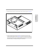
Figure 124
Battery Harness
Battery Harness