
HP SureStore E Disk Array FC60 Service Manual (A5635A)


Disk Enclosure Modules 301
Removal and
Replacement
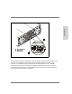
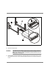
Figure 95
BCC Removal and Replacement
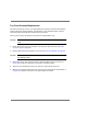
8. Remove the replacement BCC from its ESD bag.
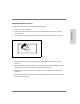
9. Set the Enclosure (Tray) ID and the DIP configuration switches to the same settings as
on the original BCC. See Figure 96.
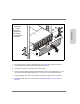
10. Install the replacement BCC into the slot:
a. Open the cam levers by pulling them out and away from the center of the module.
b. Insert the BCC into the empty slot. Orient the BCC so the cam levers are up for
installation into the top slot and down for installation into the bottom slot.
c. Push both cam levers flat against the center of the module to seat the BCC pins
firmly into the backplane connector.
d. Tighten the locking screws.
A - Locking screw
B - Cam Lever
C - BCC Slot