
HP StoreEver MSL6480 Tape Library User and Service Guide


Verifying the library configuration
Power on the library by pressing the button just below the OCP.
Verify that the library initializes correctly and that the status is Ready. Verify that the replacement
module is visible in the OCP or RMI.
Under normal operation the library configuration is saved on the base module controller. For
instructions on restoring the library configuration, see “Restoring the library configuration from a
file” (page 44).
Replace the tape cartridges in the same locations.
Replacing the robotic assembly and spooling mechanism
CAUTION: Parts can be damaged by electrostatic discharge. Keep parts in electrostatic containers
until needed. Ensure you are properly grounded when touching static sensitive components.
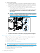
IMPORTANT: Under normal circumstances, when the library is powered off using the front power
button the robot automatically parks and locks into the base module behind the OCP. After powering
off the library and before proceeding with the robotic assembly and spooling mechanism removal,
look inside the base module window to verify that the robotic assembly is behind the OCP. If you
do not see the robotic assembly completely in the base module, see “Returning the robotic assembly
to the base module” (page 147) for troubleshooting information.
Powering off the library
Verify that all host processes are idle.
Power off the library from the front panel. Depress the power button for 5 seconds and then release
it. If the library is idle, you can release the button when the Ready LED begins flashing. If the library
does not perform a soft shutdown, depress and hold the power button for 10 seconds.
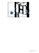
Verify that the robotic assembly is in its parked position. Look inside the base module window to
verify that the robotic assembly is behind the OCP.
Preparing to remove the robotic assembly and spooling mechanism from the base
module
WARNING! When extending a module from the library, to reduce the risk of personal injury or
damage to equipment:
• Extend the rack leveling jacks to the floor.
• Ensure that the full weight of the rack rests on the leveling jacks.
• Verify that the rack is level side to side and front to back.
• Install the rack stabilizer kit on the rack.
• Extend only one rack component at a time. Racks may become unstable if more than one
component is extended.
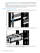
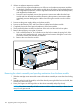
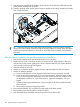
1. Loosen the front captive thumbscrews that connect the base module to the rack two full turns.
Replacing the robotic assembly and spooling mechanism 125