HP StoreEver MSL6480 Tape Library User and Service Guide Abstract This guide provides information on installing, configuring, upgrading, and troubleshooting the tape library. This guide is intended for system administrators and other users who need physical and functional knowledge of the tape library.
© Copyright 2013, 2014 Hewlett-Packard Development Company, L.P. The information contained herein is subject to change without notice. The only warranties for HP products and services are set forth in the express warranty statements accompanying such products and services. Nothing herein should be construed as constituting an additional warranty. HP shall not be liable for technical or editorial errors or omissions contained herein.
Contents 1 Features and overview................................................................................8 Front panel overview.................................................................................................................8 Back panel overview.................................................................................................................9 Tape drive back panel overviews................................................................................................
Configuring media barcode compatibility checking................................................................47 Managing license keys.......................................................................................................48 Configuring the system language.........................................................................................48 Configuring the RMI timeout................................................................................................
Identifying a failed component.................................................................................................96 Installing or replacing a tape drive............................................................................................96 Removing a tape drive........................................................................................................96 Removing a drive bay cover................................................................................................
Replacing a module..............................................................................................................118 Overview........................................................................................................................118 Saving the configuration...................................................................................................119 Unlocking the magazine...................................................................................................
The robotic assembly is stopped in an expansion module that is near the base module or is stopped directly between two modules............................................................................................147 The robotic assembly is stopped in an expansion module that is not near the base module or it cannot move vertically......................................................................................................148 Running library tests...............................................
1 Features and overview WARNING! Only trained personnel should operate this equipment. Read all documentation and procedures before installation or operation. This product is intended for installation and operation in a computer rack with the front and rear doors closed and secured. Only personnel with technical and product safety training should be provided access to the library. Such personnel are referred to as users throughout this document.
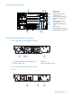
Back panel overview 1 2 3 4 5 6 7 8 10 1. Power supplies 2. Chassis fan 3. Upper expansion module interconnect port 4. USB port (base module only) 5. Ethernet port (base module only) 6. Lower expansion module interconnect port 7. Controller health status LED, green 8. UID LED, blue 9. Half-height tape drive locations 10. Module alignment mechanism 9 Tape drive back panel overviews SAS tape drive back panel overview 1 2 3 4 1. Tape drive Ethernet port (reserved for future use) 2. SAS port A 3.
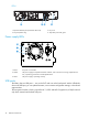
LTO-6 1 2 3 4 1. Tape drive Ethernet port (reserved for future use) 2. FC port A 3. FC port B (LTO-6 only) 4. Tape drive power LED, green Power supply LEDs 1 2 3 1. White AC power is connected. 2. Amber The power supply has experienced a fault condition, such as the fan not running, temperature too hot, or producing power that is outside specifications. 3. Green The power supply is operating correctly. USB ports The library has two USB ports — one on the OCP and one on the back panel.
Element numbering In most cases the library displays logical element numbering, with modules, tape drives, and storage slots numbered from the bottom of the library up starting with one. 3 10 9 6 2 8 7 5 4 3 1 2 1 Storage slots and mailslot elements are numbered as shown. 50 2 80 40 10 41 31 50 71 70 1 1 1. Left magazine 41 61 3 MS10 MS1 2. Right magazine with the mailslot disabled 3.
Encryption The LTO-4 and later generation tape drives include hardware capable of encrypting data while writing, and decrypting data when reading. Hardware encryption can be used with or without compression while maintaining the full speed and capacity of the tape drive and media. Encryption is the process of changing data into a form that cannot be read until it is deciphered with the key used to encrypt the data, protecting the data from unauthorized access and use.
IMPORTANT: When encryption is enabled with the encryption kit, the library will not use encryption keys from other sources, such as a key management system or application software. Disable encryption in applications writing to the library when encryption is enabled with the encryption kit. Applications that attempt to control encryption while encryption is enabled with the Encryption Kit will not be able to do so, which can cause backups or other write operations to fail.
SAS specifications The server must have an HP or third party SAS host bus adapter with an external connector. Table 4 SAS drive interface speeds LTO generation Supported speeds LTO-5, LTO-6 1.5 Gb, 3 Gb, 6 Gb The device uses multiple LUNs to communicate with the Library. Most SAS RAID controllers do not support multiple LUNs. To verify that your HBA is supported on your server and qualified for the library, see the EBS matrix on the EBS website: www.hp. com/go/ebs.
NOTE: The LTO-3 and later tape drives support both rewriteable and WORM data cartridges. Write-Once, Read-Many (WORM) data cartridges provide an enhanced level of data security against accidental or malicious alteration of data on the tape cartridge. The WORM data cartridge can be appended to maximize the full capacity of the tape cartridge, but you will be unable to erase or overwrite data on the cartridge. WORM data cartridges are clearly identified by their distinctive, two-tone cartridge color.
IMPORTANT: The bar code label should only be applied as shown, with the alphanumeric portion facing the hub side of the tape cartridge. Never apply multiple labels onto a cartridge because extra labels can cause the cartridge to jam in a tape drive. Using and maintaining tape cartridges CAUTION: Do not degauss LTO data cartridges! These data cartridges are pre-recorded with a magnetic servo signal. This signal is required to use the cartridge with the LTO tape drive.
Figure 2 Write-protecting the data cartridge 1. Write-enabled 2. Write-protected 3. Write-protect switch 4. Bar code label 5. Insertion arrow Read and write compatibility HP Ultrium data cartridges are fully supported and compatible with HP Ultrium tape products (see Backward read compatibility). Because HP Ultrium media is Ultrium logo compliant, it may be used with any other non-HP device that bears the Ultrium logo.
Command View TL software is installed on a management station. The management station can also be used to manage HP EML and ESL Tape Libraries. For best performance, the management station should be in the same physical location and on the same IP subnet as the library. Command View TL software is available for download without charge from the HP website at http:// www.hp.com/support/cvtl.
2 Installing the library WARNING! Each library module weighs 41 kg (90 lb) without media or tape drives and 71.4 kg (157.4 lb) with media (80 cartridges) and six tape drives. When moving the library, to reduce the risk of personal injury or damage to the device: • Observe local health and safety requirements and guidelines for manual material handling. • Remove tapes from tape drives before moving a module.
Table 9 Location criteria (continued) Criteria Definition Place the device near an AC outlet. The AC power cord is the product's main AC disconnect device and must be easily accessible at all times. Weight without drives or media 41 kg (90 lb) Weight with drives and media 71.4 kg (157.4 lb) Air quality The library should be placed in an area with minimal sources of particulate contamination.
You must provide a Fibre Channel cable for each tape drive in the library. The tape drive has an LC-style connector. Most supported tape drives have two FC ports. Only one port may be used at a time, but both ports can be connected for path fail over if your application supports path fail over. If you are using only one port, you can use either port. Direct connection If you plan to connect the library directly to the server, you will need a 2 Gb, 4 Gb, 8 Gb, or 16 Gb Fibre Channel HBA.
The library has a mini-SAS connector on each tape drive. The connector is keyed in location 4, which is the standard location for end devices. If you use a cable other than the one recommended for use with the product, verify that it is keyed in location 4. CAUTION: Mini-SAS connectors are keyed. Do not force a SAS cable's mini-SAS connector into the tape drive mini-SAS connector because it might be keyed differently.
Unpacking the shipping containers Before you begin, clear a level work surface near where you will place the library modules. CAUTION: If the temperature in the room where the module will be installed varies by 15º C (30º F) from the room where it was stored, allow it to acclimate to the surrounding environment for at least 12 hours before unpacking it from the shipping container.
Preparing the top and bottom modules Skip this step if you are installing a library without expansion modules. WARNING! Each library module weighs 41 kg (90 lb) without media or tape drives and 71.4 kg (157.4 lb) with media (80 cartridges) and six tape drives.
To move a library cover plate from the base module to an extension module: 1. Remove the library cover plate from the base module. a. Place the base module on a work table. If you are removing the bottom cover, gently turn the base module over so you can access the bottom of the module. b.
2. Install the cover on the expansion module. a. Place the expansion module on the work table. If the module will be the bottom module in the library, gently turn the module over so you can access the bottom of the module. b. Align all eight tabs on the cover with the slots on the module, gently push it down, and then slide the cover towards the back of the module until the spring lock at the front of the module engages by popping out. c.
b. c. d. From the inside of the rack, insert the tabs and pins on one of the brackets into the holes on the vertical support in the location shown. Use two screws to secure the bracket to the vertical support. Repeat steps b and c to install the other brackets.
3. From the front of the rack, insert the rack rails into the back and then front vertical supports. a. Position a rail according to the left-right front-rear orientation information stamped on the rail. b. Rotate the front of the rail up while inserting the rear rail hanger into the middle hole of the marked U section in the rear vertical support, and then lower the front of the rail until it is nearly level. c.
4. On the front of both rails in a square-hole rack, install a clip nut above the mounting bracket as shown For increased stability, install the retention inserts from the packet labeled Retention inserts using a T10 Torx driver. 1 2 4 3 The library has a three-part rail system: • Outer rail is installed in the rack. • Middle rail connects to the inner and outer rails so the module can be slid out of the rack. • Inner rail is attached to the module.
2. Slide the inner rails into the middle rails. Slide the module into the rack. a. Once the module is secure on the rails, remove the protective tape on the front of the module around the thumbscrews. b. Depress the release clips on both rails and then slide the module completely into the rack. If the module does not go fully into the rack the first time, pull the module back out to the lock position and insert it again. 2 3.
<4mm 4. Use your fingers or a #2 Phillips screwdriver to tighten the captive fasteners on each side of the module until they are finger tight. Do not over tighten. 5. 6. Repeat steps 2 through 4 to install the rest of the modules into the rack. Once all modules are installed, you can remove the protective film from the front of the base module. Aligning and connecting modules Skip this step if the library does not have expansion modules.
2. From the back of the library, starting with the bottom pair of modules, align each module with the module below. Repeat for each pair of modules. CAUTION: The alignment mechanism on the lowest module must be secured in the unlocked position. The library will not operate with the bottom mechanism in the locked position. a. b. Loosen the thumbscrew on the module alignment mechanism. Lower the alignment mechanism.
5. From the back of the library connect the lower module of each pair to its adjacent module using the expansion interconnect cable as shown. Installing tape drives If your library does not have tape drives installed, install the tape drives now. If the library already has a tape drive and you purchased additional tape drives, you can install them now or wait until after the library installation is complete. TIP: 1.
Connecting the Fibre Channel cables 1. Remove the FC port caps if necessary. Attach one end of the FC cable to port A on the tape drive. 2. Attach the other end of the FC cable to a switch or HBA. NOTE: Using both ports on a dual-port drive requires multi-path capability in the host application. Refer to the application documentation for information on configuring the second port. Connecting the SAS cable 1. 2. Attach the HBA end of the SAS cable into the connector on the HBA.
Powering on the library Plug the power cables into the power connectors on each module and into power outlets. TIP: The library has dual redundant power supplies. To increase redundancy, plug each power cord into a different AC power circuit. To use the RMI, connect an Ethernet cable from the Ethernet port on the library module controller to your network. 1 2 1. Power connectors 2.
Labeling and loading the tape cartridges The library will power on without cartridges, but needs cartridges before performing data read and write operations, or any tests or operations that transfer cartridges. For proper operation, use barcode labels in production environments. The library does not support the use of media without barcode labels. Using the mailslot If the mailslot is enabled, you can use it to load cartridges into the library.
4. Repeat steps 1 through 3 for each of the other magazines. Verifying the installation Verify that the library has the current firmware revision. The library firmware revision is displayed in the top left corner of the OCP and RMI screen. If necessary, update the library firmware from the OCP or RMI Maintenance > Software Upgrades > System Firmware screen.
• Enabling and configuring Command View TL integration. See Configuring Command View TL integration (page 66). • Setting up email event notification. See “Configuring event notification parameters” (page 50). • Using the HP StoreEver 1/8 G2 and MSL Encryption Kit. See “Configuring use of the MSL Encryption Kit” (page 59).
3 Operating the library The library provides two main interfaces: • Operator control panel (OCP) — With the OCP, you can monitor, configure, and control the library from the front panel. • Remote management interface (RMI) — With the RMI, you can monitor, configure, and control the library from a web browser. The RMI hosts a dedicated, protected Internet site that displays a graphical representation of the library.
TIP: Check the online help in the RMI for additional information. The help pages are updated with firmware updates and often contain up-to-date technical details that might not be contained in this document. To access RMI help, click the ? icon on the right side of the RMI top banner. Logging in to the library Figure 3 Login screen To log in to the library: 1. OCP: If the OCP screen saver is on, tap the screen.
Using the library main screen The library main screen is organized into the following regions: • Top banner — Contains the home button and displays the overall status and information about the library and user • Left pane — Displays the library identity and module status • Center pane — Provides access to operate and configure the library and to view additional status information • Right pane — (RMI only) Displays a log of recent events Top banner elements • • • — Home icon — Returns to the librar
• ◦ Firmware — The library firmware version ◦ EK Token — Information about the key server token when using the MSL Encryption Kit Module status overviews — a summary of each module’s configuration and health Click or tap the module status area to select the module. ◦ Module health icon – The green check mark Status OK icon indicates that the module and each of its components are fully operational and that no user intervention is required.
• Operation — (Administrator user only) Click or tap to access operation functions. See “Operating the library” (page 79). • Status — Click or tap to access status information. See “Viewing status information” (page 83). • Service Area — (Service user only) Click or tap to access to functionality restricted to service engineers. Both the service and administrator passwords are required to log in as the service user.
3. 4. Select the destination location: • RMI — (RMI only) Downloads the configuration file to the browser or system running the RMI. • USB Device Front — Downloads the configuration file to a USB flash drive inserted into the USB port on the front of the library. • USB Device Rear — Downloads the configuration file to a USB flash drive inserted into the USB port in the back of the library. Click Save. Restoring the library configuration from a file 1. 2. 3. 4. 5.
Setting the timezone 1. Click Time Zone. A list of continents, countries, and regions is displayed. When an item preceded with ‘>’, for example > US, is selected, a submenu is displayed in the next column. Figure 5 Setting the Time Zone 2. 3. 4. Expand the timezone list, as necessary, until a location with the appropriate timezone is visible. Select a location with the appropriate timezone. Click Submit. Setting the date and time format 1. Click Date/Time Format.
3. Select a date format: For example, July 30, 2013 is displayed as: 4. • DD.MM.YYYY — 30.07.2013 • MM/DD/YYYY — 07/30/2013 • YYYY-MM-DD — 2013-07-30 Click Submit. Setting the date and time 1. Click Set Date/Time. Figure 7 Setting the date and time 2. Set the time and date. To set the time and date manually: a. Enter the time in the configured time format. b. Enter the date or select it from the calendar. To synchronize the time and date with the computer running the browser, click Now. 3.
1. Click SNTP. Figure 8 Configuring the SNTP server 2. 3. 4. Click SNTP Enabled. Enter the SNTP server address. Click Submit. Configuring media barcode compatibility checking From the Configuration > System > Media Barcode Compatibility Check screen you can enable or disable the barcode media ID check.
Managing license keys License keys register licensed library functionality. From the Configuration > System > License Key Handling screen you can add and view license keys. 1. 2. Navigate to the Configuration > System > License Key Handling screen. In the Add License Key pane, enter the License Key and then click Add License. Configuring the system language The RMI is available in English and Japanese.
Figure 10 Configuration > Network screen 1. 2. 3. 4. Navigate to the Configuration > Network screen. Configure or update the Host Name and Domain Name. The RMI URL is .. Select the internet protocol to use for the library. Configure the settings for the selected internet protocol. To have the library obtain an internet address from a DHCP server, select the DHCP or Stateless method. 5. Click Submit.
Figure 11 Configuration > Network Management > SNMP screen • SNMP Enabled — When checked, the library can be managed by computers listed in the SNMP Target IP Addresses field. • Community Name — A string used to match the SNMP management station and library. It must be set to the same name on both the management station and the library. The default community name is public. • SNMP Targets — List of configured SNMP targets. To add an SNMP target or edit information for an SNMP target: 1.
Figure 12 Configuration > Network Management SMTP screen • SMTP Enabled — Check to enable SMTP. When checked, the remaining configurations are active. • Notification Level— The types of events for which the library should send e-mail ◦ Inactive — No events are sent. ◦ Critical — Only critical events are sent. ◦ + Warnings — Only critical and warning events are sent. ◦ + Configuration — Only critical, warning, and configuration events are sent. ◦ + Information — All events are sent.
• Mailer Name — Name of the sender of the e-mail. • Email Subject — Subject line for the e-mail message. • Email Address — Return address to use for the e-mail message. • Authentication Required — When checked, a username and password are required to access the SMTP server. • Username — User account for logging into the SMTP server when authentication is required. • Password — Password associated with the Username when authentication is required.
• • ◦ LTO 5: Ultrium 3000, Ultrium 3280 ◦ LTO 6: Ultrium 6250 Drive form factor ◦ HH — half height ◦ FH — full height Drive interface ◦ FC — Fibre Channel ◦ SAS — Serial Attached SCSI • (Modified) — When present indicates that a setting has been changed. To apply the changes, click Submit. To reset all changed fields to their previously saved values, click Undo. • Pwr — Indicates whether the drive is currently powered on or off.
library communication continues during the transition. Using this screen is easier than changing the active and control path drives in the Expert Partition Wizard. NOTE: 1. 2. This feature only applies to Basic CPF and is not used when Advanced CPF is enabled. Click Failover. Click Submit. Enabling or disabling mailslots The Configuration > Mailslot screen lists each of the mailslots and shows whether each is enabled or disabled.
• Magazine slots are allocated in five-slot groups. • Mailslots must be enabled for a module before they can be allocated to a partition. A partition does not need to have a mailslot. If a partition does not have a mailslot, the magazine must be accessed to import or export cartridges. Opening a magazine takes the library off line. Although the mailslot magazine is shared between partitions, the mailslot elements are assigned individually to partitions.
7. left, the device will report 123456. If alignment is right, the device will report 345678. The default is left. Check Auto Clean to enable the auto cleaning feature. When enabled, the library automatically initiates a cleaning operation when media is unloaded from a drive that requires cleaning instead of creating a warning event when a drive requires cleaning. When auto cleaning is enabled, the library must have an unexpired labeled cleaning cartridge.
NOTE: The industry standard length for LTO barcode labels is eight characters. Barcode labels longer than eight characters might scan incorrectly, particularly if they are not high quality labels. The maximum barcode label length for the HP StoreEver 1/8 G2 Tape Autoloader and MSL2024, MSL4048, MSL8048, and MSL8096 Tape Libraries is 15 characters. 4. 5.
All drive port types, A and B for full height drives, must be configured as Fabric. Any drive that is not set to Fabric will be configured as Fabric by the Expert Partition Wizard. If CPF is disabled, the ports remain in Fabric mode until they are manually reconfigured. • Enable — Advanced Control Path Failover (ACPF) — When selected, the host operating systems and library work together to handle error recover and path failover for the partition at a level below the backup application.
Configuring the encryption key manager type The Configuration > Encryption screen displays the available data encryption key manager types along with the status of each type. Only one encryption manager type can be configured for the library at a time and it will be used for all tape drives and partitions. NOTE: Encryption configuration changes cannot be made while media is loaded in any drive in the library. To change the configured encryption key manager, select the key manager and then click Submit.
1. 2. 3. Navigate to the Configuration > Encryption > USB — MSL Encryption Kit screen. Verify that the correct token is available. Enter the Token PIN and then click Submit. Changing the token PIN Figure 16 Changing the PIN or token name 1. 2. 3. Navigate to the Configuration > Encryption > USB — MSL Encryption Kit screen. Expand the Pin Management section. Enter the current and new PINs. The PIN must be at least 8 characters and no longer than 16 characters.
TIP: Using a descriptive name, including the dates when the keys on the token were used, could be helpful if your log of tapes written with keys on the token is lost. 4. Click Submit. Generating a new write key Figure 17 Managing encryption keys 1. 2. 3. Navigate to the Configuration > Encryption > USB — MSL Encryption Kit screen. Expand the Key Management section. Click Apply.
3. 4. Set the policy for the new key generation frequency, and the date and time this will occur. Click Submit to apply your selections. NOTE: A key is not generated when the library time is advanced past a time when a new key would have been generated. If you advance the library time, check the automatic key generation policy to see whether a new key is needed, and if so, manually generate it. One new key is generated if the library is off at a time when a new key would have been automatically generated.
Figure 18 Enabling or disabling encryption 1. 2. 3. Navigate to the Configuration > Encryption > USB — MSL Encryption Kit screen. Expand the Enable/Disable Encryption section. Click Enable or Disable. Configuring use of the ESKM With the ESKM Wizard you can configure use of the HP Enterprise Secure Key Management server with the library.
2. 3. 4. 5. 6. The Wizard Information screen displays information about the wizard. If the library configuration is complete, click Next. The Certificate Authority Information screen displays prerequisites for using the ESKM certificate. When the prerequisites are met, click Next. The Certificate Authority Certificate Entry screen displays instructions for obtaining the certificate for the ESKM server. Follow the instructions to copy the certificate from the management console.
Using the KMIP Wizard 1. 2. 3. 4. 5. 6. 7. In the Configuration area, click KMIP Wizard in the Encryption menu to start the wizard. The Wizard Information screen displays information about the wizard. If the library configuration is complete and the KMIP server is available on the network, click Next. The Certificate Authority Information screen displays prerequisites for using the KMIP certificate. When the prerequisites are met, click Next.
Figure 19 Configuration > User Accounts screen Select the user and then enter the new password twice. The password must contain 8-16 characters, which can include upper and lower case letters, numbers, and special characters Restricting RMI access for the administrator and security users To restrict RMI access for the administrator and security users, check Restricted Remote Management Interface (RMI) Login.
Figure 20 Configuration > Command View TL screen Library information • Name — The name of the library that will be displayed in the Command View TL interface. The default is HP MSL6480 . • Serial Number — The serial number of the base module. This cannot be modified. • Management URL — The URL of the management station, including port. For example: http://192.0.2.24:8099. Product information • Name — HP MSL6480. This cannot be modified. • Version — Library firmware version.
Figure 21 Configuration > Web Management screen Enabling and configuring Secure Manager With Secure Manager, you can configure hosts and drives into access control groups that are managed by the library. With Secure Manager enabled, the drives are not visible to hosts that are logged in to the SAN and so the host will not see the drives by default. For the host to see a drive, the host must be configured into an access control group with the drive.
2. In the Access Group Name screen, enter the Group Name, and then click Next. The library discovers and displays the attached host WWPNs. The SAN switch RMI that is being used can also be referenced to see the WWPN-to-port association to help determine which servers are attached. 3. In the Access Group Hosts screen, select the hosts for the group and then click Finish.
Configuring hosts To configure device access, click Edit next to Host Configuration. From this screen you can create a host that is not on physically on the SAN, modify the name of a host used within Secure Manager, or delete a host from access by Secure Manager. IMPORTANT: Once the host is added to the SAN, verify that the WWPN of the host matches the WWPN value that was pre-configured. To create a host: 1. Click Create Host, and then click Next. 2.
To run the system test, navigate to the Maintenance > Library Tests > System Test screen, select the number of cycles and then click Start Test. Performing the slot to slot test The slot to slot test randomly exchanges cartridges between slots to verify that the library is operating correctly. At the end of the test the cartridges are NOT returned to their original slots. If a tape is moved to an incompatibly drive, the drive will reject the tape, as designed.
Figure 24 Maintenance > Library Tests > Element to Element Test screen To run the element test: 1. Navigate to the Maintenance > Library Tests > Element to Element Test screen. 2. Select a cartridge from the Source Elements list. To select from a subset of the cartridges: a. Click Filter On. b. Enter characters into the search box and then click Search. The Source Elements list is updated to only include cartridges with a barcode label including the search characters. 3. 4. 5.
To run the wellness test, navigate to the Maintenance > Library Tests > Wellness Test screen and then click Start Test. Performing the robotic test The robotic test performs a full inventory and exercises all robotic assembly movements and sensors. Figure 25 Maintenance > Library Tests > Robotic Test screen To run the robotic test, navigate to the Maintenance > Library Tests > Robotic Test screen and then click Start Test.
Figure 27 Maintenance > Logs and Traces > View Logs screen The log entries are displayed in order of most recent to oldest. The log entries contain a date and time code, event code, severity, component identifier and event details. The format for the date and time is: YY.MM.DD HH.MM.SS.ss. • YY.MM.DD — The date displayed as Year.Month.Day • HH.MM.SS.ss — The time displayed as Hour.Minute.Second.
Figure 29 Maintenance > Software Upgrades > System Firmware screen To update library firmware from the RMI, click Choose File and select the firmware file from the local computer. To update the library firmware from the OCP: 1. Copy the firmware file to a USB flash drive. 2. Insert the USB thumb drive into the USB port on the front of the library. The library detects the USB drive. 3. 4. Select the firmware file. Click Start Upgrade.
Figure 30 Maintenance > Software Upgrades > Drive Firmware screen To update drive firmware from the RMI: 1. Navigate to the Maintenance > Software Upgrades > Drive Firmware screen. The tape drives are organized by drive type. 2. Expand the appropriate drive type and select one or more of the tape drives. 3. Click Choose File, and then select the file from the local computer. 4. Click Submit.
Figure 31 Maintenance > Download Support Ticket screen To download a drive support ticket: 1. Expand the drive support ticket list, if necessary, by clicking the down arrow on the left side. The drive list displays: 2. • Drive — The drive number. Drives are numbered starting with one from the physical bottom of the library to the top.
To download a library support ticket: 1. Expand the Library Support Ticket area, if necessary, by clicking the down arrow on the left side. 2. Click Save. Rebooting the library From the Maintenance > System Reboot screen, click Reboot. Figure 32 Maintenance > System Reboot screen Controlling the UID LED The UID LEDs are a pair of blue LEDs — one on the OCP and the other on the base module controller. The UID LEDs are useful for identifying the library in a data center.
Operating the library Click or tap the Operations button on the Home screen to access the operations features. Moving media From the Operation > Move Media screen you can move a tape cartridge located in a source element to an available destination element within the same partition.
To perform a different search or display all of the available cartridges, click Barcode Filter Off. Moving a cartridge 1. 2. 3. Select the cartridge from Source Elements. Select the destination location from Destination Elements. Click Submit. Opening the mailslot From the Operation > Open Mailslot screen you can see the status and unlock any enabled mailslot in the library. Figure 36 Operation > Open Mailslot screen To open a mailslot, click Unlock for the appropriate mailslot and then click Submit.
Figure 37 Operation > Open Magazine screen To unlock a magazine, click Unlock for the magazine and then click Submit. The library will release the lock. You can then open the door and pull the magazine out of the library to access the storage slots. NOTE: Opening a magazine will take the library off line. NOTE: The magazines will relock after 30 seconds. Cleaning a tape drive The tape drive monitors its need for cleaning, reporting a cleaning request as an event.
Figure 38 Operation > Clean Drive screen 1. Select a cleaning cartridge from the Source Elements list. The library uses the barcode label to identify cleaning cartridges. If no cleaning cartridges are available, load one into a mailslot or magazine slot. 2. Select the tape drive to be cleaned from the Destination Elements list. Tape drives currently containing a cartridge are not listed. To clean a tape drive not listed, move the cartridge out of the drive. 3.
NOTE: If the drive has difficulty ejecting the cartridge, suspect bad or damaged media. Figure 40 Operation > Force Drive Media Eject screen 1. 2. 3. 4. Navigate to the Operation > Force Drive Media Eject screen. Select the drive in the Source Elements list. Select the destination in the Destination Elements list. Click Submit. Viewing status information To access the status area, from the Home screen, click or tap Status.
• WWide Node Name — A world wide unique identifier that the library reports over SCSI and can be used by operating systems or software applications to identify and track the library. • Product ID — Always MSL6480 • Firmware Revision — Version of the currently installed library firmware • Robotic Firmware Revision — Version of the currently installed robotic assembly firmware. The robotic assembly firmware is bundled and installed with the library firmware.
Using list views The inventory lists display each of the elements, such as slots and tape drives, with information about the cartridge stored in the element. To see the elements organized by module, navigate to the Status > Cartridge Inventory > List View screen. To see the elements organized by logical library or partition, navigate to the Status > Partition Map > List View screen.
• Full — X if a cartridge is using the element • Gen — LTO generation of the cartridge • Partition — The partition number Filtering by barcode label To filter the list based on barcode label, enter characters in the filter box and then click Search. 1. Click Filter On. The search box is displayed. 2. Enter characters into the search box and then click Search. The characters can be anywhere in the barcode label. The search characters are not case sensitive. There are no wildcards.
Viewing library or partition configuration settings In the Status > Partition Map > Configuration Status screen you can see the current configuration settings for a partition. Expand the sections for additional information. NOTE: The configurations listed in this screen can be modified using the Expert Partition Wizard. See “Configuring library partitions” (page 54).
Figure 42 Status > Drive Status screen • Drive number — Drives are numbered starting with one from the bottom of the library up. The drive currently hosting the SCSI communication for the library is designated with (LUN). • Serial number — The serial number assigned to the tape drive by the library. This serial number is reported to host applications.
• • Status icon ◦ A green circle with a check mark indicates that the drive is fully operational and that no user intervention is required. ◦ A yellow triangle with an explanation point indicates that user attention is necessary, but that the drive can still perform most operations. ◦ A red circle with an X indicates that user intervention is required or the drive is not capable of performing some operations. Drive status ◦ Write — The drive is performing a write operation.
• Media Removal — Whether the media can be removed from the drive or not. Many host applications prevent media removal while accessing the cartridge in the tape drive. • Data Compression — Indicates whether the drive is using data compression. • Data Path Failover ◦ Basic — Basic Data Path Failover is enabled. ◦ Disabled — DPF is not enabled for the drive. ◦ Unlicensed — A Data Path Failover license has not been added to the library.
Viewing network status Figure 43 Status > Network screen In the Status > Network screen you can see: • Host Name — Library hostname • Domain Name • Protocol — IPV4 or IPv6 • MAC Address— A unique identifier for the library controller network interface • Link Status — Enabled or disabled • Link Speed — Speed of the Ethernet connection to the library • Duplex — Enabled or disabled IPv4 settings • DHCP — When Enabled, the library requests an IP address from a DHCP server each time the library is
• Gateway — The gateway used when DHCP is not enabled. • DNS 1 • DNS 2 IPv6 settings • Stateless Addressing — When Enabled, the device will generate an address for itself based on the routing information obtained from a router advertisement and the MAC address. The device can manage up to five global addresses at the same time, which can be assigned from different routers. • Static Addressing — When Enabled, the library will use a statically-configured address.
Viewing encryption status Navigate to the Status > Security screen to see the status of any key servers configured for use with the library, as well as the encryption status of the tape drives and partitions. Figure 45 Status > Security screen • USB — MSL Encryption Kit — Status of the MSL Encryption Kit key server token. NOTE: The key server token should only be inserted in the rear USB port in the base module. • ESKM — Status of the connection to the ESKM server.
Viewing Secure Manager status Navigate to the Status > Secure Manager screen to see the currently defined Secure Manager access groups. Hosts • Name — Host name used with Secure Manager. The name is defined when the host is created in Secure Manager and can be modified. • WWPN — World Wide Port Number. The WWPN is defined when the host is created in Secure Manager. To modify the WWPN, remove and then recreate the host. Drives 94 • Drive number — The drive number assigned by the library.
• • Form factor ◦ HH — Half height ◦ FH — Full height Drive interface ◦ FC — Fibre Channel ◦ SAS — Serial Attached SCSI • Serial# — The serial number assigned to the tape drive by the library. • Partition — Library partition to which the drive is assigned. • Available ports — Displays the available ports on the drive. • WWPN_A, WWPN_B — The world wide port name, a unique identifier for each FC interface.
4 Upgrading and servicing the library CAUTION: Slide/rail mounted equipment is not to be used as a shelf or a work space.
2. Verify that the tape drive assembly LED is off, and then remove the FC cable from the tape drive. 3. Loosen the blue captive thumbscrews on the tape drive. Pull straight back on the tape drive handle while supporting the bottom of the drive to remove it from the unit. 1 2 CAUTION: Support the bottom of the tape drive when removing it to avoid damaging any of the internal connections. Removing a drive bay cover If you are adding a tape drive: 1. Identify the location for the tape drive.
2 1 1 Installing the new tape drive 1. 2. Align the guides on the side of the drive assembly with the guide rails in the drive bay. Slowly insert the new tape drive into the drive bay while supporting the drive assembly. The tape drive should be flush with the back panel of the device. Tighten the captive thumbscrews with your fingers until the tape drive is secure. 2 1 Connecting the SAS cable 1. 98 Attach the HBA end of the SAS cable into the connector on the HBA.
2. Connect the drive end of the cable. • If you are using a cable with a single connector on each end, attach the other end into the connector on the tape drive. • If you are using a SAS fanout cable, attach one mini-SAS connector into the connector on each tape drive. The unused ends of the SAS fanout cable are single channel and not suitable for use with disk arrays. Use the other ends to connect tape drives, or coil and secure them to the rack to minimize stress on the connectors.
Verifying the installation 1. 2. 3. 4. To ensure proper operation, install drive bay covers on any unused drive bays. Power on the drive from the OCP or RMI, if necessary. Confirm that the library recognizes the new tape drive by checking the OCP or RMI. The new drive should appear in the module status overview area on the left side of the screen. Use HP Library & Tape Tools (L&TT) to verify that the system sees the tape drive and that tape drive has the current firmware. Update the firmware, if necessary.
Moving a cover to the new module The library has removable top and bottom covers. When adding a module, you must move either the top or the bottom cover to the new module. The two covers are identical and the process for removing and installing them is the same for the top and bottom of the module. See “Preparing the top and bottom modules” (page 24) for details; while this procedure refers to moving a cover from the base module, the information is the same for moving a cover from an expansion module.
3. Verify that the module has been installed directly above or below its adjacent module and is contained within the correct 6U volume. Verify that the gap between modules is less than 4mm on both sides of the front of the modules. The gap in the back must be less than 5mm. If the gap is larger or varies side to side: • Confirm that both rack rails are properly located within the U volume. • Confirm that both rack rails are properly seated in the rack vertical column.
Aligning and connecting the module Aligning the new module with the library ensures that the robot can move freely between the modules. The library will not operate unless the alignment mechanism is in the locked position. See “Aligning and connecting modules” (page 31) for details. Connect the power cords Plug the power cords into the two power supplies in the new module. TIP: The module has dual redundant power supplies. To increase redundancy, plug each power cord into a different AC power circuit.
9. Replace the cables and lock the alignment mechanisms. 10. Connect the power cords, power on the library, and verify the operation. 11. Replace the tape cartridges. For instructions for these steps, see “Replacing a module” (page 118) and “Installing the library” (page 19). When moving a library to a different physical location: • Always remove all tapes from the drives and magazines before moving the library.
1 2 Installing the new power supply 1. 2. 3. 4. Position the new power supply onto the alignment rails. Slide the power supply into the library until it is flush with the back panel of the library. Tighten the blue captive thumbscrews with your fingers to secure it to the library. Attach the AC power cord to the new power supply.
Verifying the power supply installation and operation 1. Verify that the new power supply is operating properly by checking the power supply LEDs: • The white (1) and green (3) LEDs should be lit. • The amber (2) LED should be unlit. 1 2 3 2. 3. Using the OCP or RMI, confirm that the power supply is operating correctly; the event that indicated the power supply was faulty should be cleared. If the UID LEDs are still illuminated, deactivate them using the OCP or RMI.
Powering off the library Verify that all host processes are idle. Power off the library from the front panel. Depress the power button for 5 seconds and then release it. If the library is idle, you can release the button when the Ready LED begins flashing. If the library does not perform a soft shutdown, depress and hold the power button for 10 seconds. Verify that the robotic assembly is in its parked position. Look inside the base module window to verify that the robotic assembly is behind the OCP.
2 1 Verifying the base or expansion module controller installation 1. Power on the library. The first time the library boots with the new base module controller, the library displays the OCP calibration test. Complete the touch panel calibration test, ensuring that you only press the location on the OCP that is requested by the test.
5. If replacing the base module controller, upgrade the firmware if necessary. To find the most up-to-date firmware version, visit the http://www.hp.com/support website. If necessary, download the firmware files. Update the firmware from the RMI Maintenance > Software Upgrades > System Firmware screen. 6. If replacing the base module controller, verify that the configuration settings are correct. If necessary restore the settings from a file of saved settings, or re-enter them using the OCP or RMI.
1 2 Installing the new chassis fan assembly 1. 2. 3. 110 Align the tabs on the library with the slots at the top of the chassis fan assembly. Push in the chassis fan assembly until it is flush with the back panel of the library. Tighten the blue captive thumbscrews with your fingers to secure it to the library.
2 1 Verifying the chassis fan assembly installation 1. 2. Verify that the new chassis fan assembly is installed properly by checking the OCP or RMI; the event that indicated the chassis fan assembly was faulty should be cleared. If the UID LEDs are still illuminated, deactivate them using the OCP or RMI. Replacing a drive power board CAUTION: Parts can be damaged by electrostatic discharge. Keep parts in electrostatic containers until needed.
1 2 3. Slowly slide the drive power board out of the library. 1 2 Installing the new drive power board 1. 2. 3. 4. 5. 6. 7. 112 Position the new drive power board onto the alignment rails. Slide the drive power board into the library until seated firmly. Push the latch up until it snaps into place; when the drive power board is installed correctly, the latch will not be loose. Align the tabs on the library with the slots at the top of the chassis fan assembly.
2 1 2 1 Replacing a drive power board 113
Powering on the library Power on the library by pressing the power button on the base module just below the OCP; the green light will illuminate. When the library is powered on, it inventories the tape cartridges in the magazines, checks the firmware version on all modules, configures the tape drives, confirms the presence of the existing modules, and searches for any new modules. Verifying the drive power board installation 1. Verify that all drives that are present are powered on: a.
Using the RMI 1. 2. Log in as an administrator. On the home screen, click Open Magazine. 3. Click Open in the left or right magazine column within the module containing the magazine to be opened. CAUTION: Wait until the RMI indicates that the magazine has been unlocked before attempting to remove it. Pulling on the handle while the library is unlocking the magazine might damage the library. 4. Open the magazine access door.
3. Slowly pull the magazine handle until the magazine is free of the latch. Removing the tape cartridges 1. Slowly pull the magazine handle until the magazine is fully extended. 2. Remove the tape cartridges noting their locations within the magazine. You will place them in the same locations in the new magazine after it is installed. Removing the magazine 1. 2. 116 Push the magazine approximately 12 mm (0.5 inches) back into the module to remove tension from the release mechanism.
3. Use one hand to completely remove the magazine from the module while using the other hand to support the bottom. Installing the magazine 1. 2. 3. 4. 5. Position the upper and lower magazine rails onto the alignment rails. Push in slowly until the magazine rails are properly seated and the magazine is only slightly extended (stop before locking the magazine). Pull the magazine back out until fully extended. Load the tape cartridges into the new magazine in the same locations they were in previously.
Verifying the magazine installation and operation Using the OCP or RMI: 1. Confirm that the replaced magazine is closed. 2. Confirm that the cartridges in the replaced magazine are inventoried. If you replaced the right magazine, confirm that the cartridges in the mailslot are inventoried. 3. If you replaced the right magazine, unlock the mailslot using the OCP or RMI, pull it out, and push it back in. Replacing a module WARNING! Each library module weighs 41 kg (90 lb) without media or tape drives and 71.
1. 2. 3. 4. 5. 6. 7. 8. Save the library configuration. Remove tape cartridges and power off the library. Remove all the components from the module and disconnect the power cords and cables. Remove the module from the rack. Install the replacement module into the rack. Replace the components and cables. Connect the power cords, power on the library, and verify the operation. Replace the tape cartridges.
2. Remove the expansion interconnect cables from the module being replaced and from the modules connected to it. NOTE: Completely removing the cables from both ends prevents damaging the expansion interconnect cables during module removal and replacement. 3. 4. Remove any SAS, FC, or Ethernet cables from the module being replaced. Remove the USB device, if present. Removing the tape drives Remove any tape drives from the module being replaced.
1. If you are a module that has a module immediately above and/or below it: a. From the front of the library, use your fingers to loosen the captive thumbscrews two full turns on the module and its adjacent modules. b. From the back of the library, unlock the alignment mechanisms connecting the module with the adjacent modules and secure the alignment mechanisms in the unlocked position. 2 1 3 2. 3.
“Preparing the top and bottom modules” (page 24) for details; while this procedure refers to moving a cover from the base module, the information is the same for moving a cover from an expansion module. The replacement module is shipped with a bottom cover plate but not a top cover plate. Move the cover plates as necessary so the replacement module has the cover plates in the same location as the empty module and the empty module has a bottom cover plate. Installing the module into the rack 1.
Replacing a module 123
4. If there are adjacent modules: a. From the front of the library, use your fingers or a #2 Phillips screwdriver to loosen the captive thumbscrews on the replacement module and all modules above it two full turns. b. From the back of the library, starting with the replacement module and the one below it, align the modules and lock them together. Repeat for each pair of modules. i. Use your fingers to loosen the thumbscrew on the alignment mechanism that will connect the upper module with the lower module.
Verifying the library configuration Power on the library by pressing the button just below the OCP. Verify that the library initializes correctly and that the status is Ready. Verify that the replacement module is visible in the OCP or RMI. Under normal operation the library configuration is saved on the base module controller. For instructions on restoring the library configuration, see “Restoring the library configuration from a file” (page 44). Replace the tape cartridges in the same locations.
2. If there are adjacent expansion modules: a. Loosen the front captive thumbscrews two full turns on the adjacent expansion modules. b. On the back of the base module and the module above (if present), loosen the thumbscrews on the alignment mechanisms, move the alignment mechanisms into the unlocked position, and retighten the thumbscrews. c. Disconnect and completely remove the expansion interconnect cables from the base module and from the adjacent modules.
1 2 2 4. 5. Lift the robotic assembly gently from the module and place it on top of the module on the right side (opposite the spooling mechanism) and slightly to the front. Take care not to damage the spooling cable. On the top of the robotic assembly where the spooling cable is attached, use a small flat head or Torx screwdriver driver to press and push the small latch that unlocks the spooling cable. Note where the end of the spooling cable pivots in the robotic assembly.
9. While pressing the latch near the top of the spooling mechanism, pull the entire spooling mechanism gently up until you see it clear the narrow part of the keyhole in the back left of the metal wall. It may help to push up from the bottom with your other hand. 10. Pull the spooling mechanism toward the front of the module until it disconnects and remove it from the module. 1 2 Installing the robotic assembly and spooling mechanism into the base module 1. 2. 3. 4.
5. 6. 7. Each corner of the robotic assembly has a gear with two protruding pins. Rotate one of the gears on the robotic assembly so that the two pins are aligned horizontally. Place the gears of the robotic assembly into the grooves on the inside corners of the module. Confirm that all of the pins are touching the outside of the grooves. Push the robotic assembly down slowly until the platform of the robotic assembly is approximately 7.5 cm (3 inch) lower than the top of the module.
9. Standing at the right side of the module, remove the end of the spooling cable that connects to the robotic assembly from its cradle. 10. Place the spooling cable into the grooves where it attaches to the robotic assembly and rotate until it snaps into place.
Powering on the library Power on the library by pressing the power button on the base module just below the OCP; the green light will illuminate. When the library is powered on, it inventories the tape cartridges in the magazines, checks the firmware version on all modules, configures the tape drives, confirms the presence of the existing modules, and searches for any new modules. Verifying the installation Verify that the library powers on and initializes correctly, and that the status is Ready.
2 4 1 3 5 6. If removing a base module bezel, disconnect the OCP cable. Installing the bezel 1. If installing a base module bezel, connect the OCP cable to the new OCP. Ensure that the OCP cable is correctly routed in the channel behind the clear plastic window. 2. 3. Place the bottom tabs of the bezel into the slots in the bottom of the module. Rotate the bezel and snap in the top corners.
Replacing magazine access doors Removing the magazine access doors 1. 2. 3. Insert a small flat head screwdriver into the slot directly above the top hinge. Use the screwdriver to pry the hinge free of the module while pulling the door toward you. Remove the door from the module. 2 1 3 4 Installing the magazine access doors NOTE: 1. 2. 3. 4. The doors are identical and can be mounted on either side of the module. Orient the door so that the hinges are to the outside of the module.
5 Troubleshooting CAUTION: This library is designed to operate when installed in a rack using the rack rail kit. Operating the library without installing it in the rails, such as on a table or rack shelf, could result in library errors. Placing any weight on top of the library might also cause errors. Fibre Channel connection problems Full height tape drives can only be installed in the very top, very bottom, or middle pair of half-height drive bays.
• • If neither the application software nor operating system detects the tape drive, or they do not detect both the tape drive and the library: ◦ Verify that all SAS cables are securely connected on both ends. If the mini-SAS connectors that connect to the tape drive and some HBAs will not plug in, check the key. The mini-SAS connector on the tape drive is keyed at location four, which is the standard location for end devices.
with your SAS host adapter manufacturer, backup application vendor, or the EBS compatibility matrix at www.hp.com/go/ebs. • Verify that your HBA is supported by the host computer and qualified with the library. • Ensure you are using a compatible, high-quality cable. See the product QuickSpecs for a list of supported cables. Operation problems Table 12 Power problems Problem Solution Device does not power on. 1. Check all power cord connections. 2. Check the LEDs on the power supplies. 3.
Table 14 Tape movement problems (continued) Problem Solution 1. Unlock the magazine from the Operation > Open Magazine screen and extend it to access the storage slot. 2. Grasp the cartridge and remove it from the storage slot. Some tapes need to be inserted and removed several times to condition them for free movement in and out of the magazine. 3. Check the barcode label and verity that it is secure to the cartridge. 4. Check the cartridge for damage. 5. Check the storage slot for damage.
Table 16 Attention LED is lit (continued) Problem Solution A cartridge recently imported from a Media that is moved from one environment to another can cause issues until it different environment is causing issues. has acclimated to the new conditions. A cartridge should be acclimated for at least 24 hours before being used, particularly if it has been stored at a substantially different temperature or level of humidity than the device.
Table 18 RMI network connection issues Problem Solution Cannot connect to the RMI • Verify that the Ethernet cable is connected to the base module’s module controller board and to the LAN. • Verify that the link LED on the RJ45 (LAN) connector is lit when the device is powered up. If the LED is not lit, the device is not communicating with the LAN. See your network administrator for help.
Average file size The hard drive must seek to the position of a file before it can start reading. The more time the disks are seeking to files, the lower the performance. Therefore, if the average file size is small, the read performance will be lower. To determine the average file size, divide the size of the backup by the number of files.
• Do not back up individual mailboxes. • Do not back up specific records or do a record-by-record backup. • Do not back up when the database is in heavy use. Connection from the archive/backup host server to the library For the best performance, the connection from the host server to the library must have enough bandwidth to provide enough data to keep the tape drive streaming.
Finding event information on an L&TT support ticket or report An L&TT support ticket or report contains detailed information about the device configuration, along with errors and warnings. The support ticket and report contain the same information. The report is easier to read, but must be generated and read on the host computer. The support ticket can be downloaded from the device and then viewed on any computer with L&TT installed. To generate and view a report or support ticket from L&TT: 1.
Figure 46 Support ticket in viewer Expand HP Event Logs to see events divided into three categories: • Events in the last 24 hours • Events in the last 31 days • Events older than 31 days Set the Current Detail Level to see additional types of events: • Normal will only show critical events or hard errors. • More details will also show warning and configuration events. • Everything shows all events. Critical events are designated with a STOP sign icon. Expand an event for more information.
Unlocking the magazine HP recommends unlocking the magazine using the OCP or RMI. If these methods fail, or if a magazine needs to be removed when the power to the device is off, you can release the magazine manually. Only one magazine or mailslot can be open at a time. NOTE: As a best practice, perform this procedure while applications are idle. While the magazine is extended, the library robotic assembly cannot move media. Using the OCP or RMI 1. 2. Log in as an administrator.
4. Open the magazine access door. NOTE: If not removed, the magazines and the mailslot will relock after the time configured on the Configuration > Mailslots screen. The default is 30 seconds. Using the manual release 1. 2. Open the magazine access door. Insert a small flat head screwdriver or Torx driver into the appropriate magazine release hole and gently push the tab in. IMPORTANT: device. 3. Do not exert force once you encounter resistance.
Unloading a stuck tape If the tape is stuck in a tape drive, eject the tape from the drive from the Operation > Force Drive Media Eject screen. If a tape is stuck in a magazine, open the magazine, grasp the cartridge, and pull it out of the storage slot. Identifying a failed component Using the OCP or RMI: 1. Activate the UID LEDs from the Maintenance > UID LED Control screen.
Returning the robotic assembly to the base module If you have powered off the library and the robotic assembly did not return to its park position in the base module behind the OCP: 1. Power on the library by pressing the power button on the base module just below the OCP. 2. From the RMI, return the robotic assembly to its park position from the Maintenance > Move Robotic to Base Module screen. 3. Power off the library from the front panel. Depress the power button for 5 seconds and then release it.
7. 8. Install the new robotic assembly and spooling mechanism; see “Installing the robotic assembly and spooling mechanism into the base module” (page 128). Slide the base module back into the rack; see “After the robotic assembly and spooling mechanism installation” (page 130). The robotic assembly is stopped in an expansion module that is not near the base module or it cannot move vertically 1. 2. 3. Remove the left magazine of the base module; see “Removing the magazine” (page 116).
Running library tests The library provides tests to verify library operations. • System test — exercises overall library functionality by moving cartridges within the library. Cartridges are returned to their original locations. See “Performing the system test” (page 70). • Slot to slot test — randomly exchanges cartridges within the library. Cartridges are NOT returned to their original locations. See “Performing the slot to slot test” (page 71).
6 Support and other resources Contacting HP For worldwide technical support information, see the HP support website: http://www.hp.
WARNING! CAUTION: IMPORTANT: NOTE: TIP: Indicates that failure to follow directions could result in bodily harm or death. Indicates that failure to follow directions could result in damage to equipment or data. Provides clarifying information or specific instructions. Provides additional information. Provides helpful hints and shortcuts. Rack stability Rack stability protects personnel and equipment.
7 Documentation feedback HP is committed to providing documentation that meets your needs. To help us improve the documentation, send any errors, suggestions, or comments to Documentation Feedback (docsfeedback@hp.com). Include the document title and part number, version number, or the URL when submitting your feedback.
A Acronyms and abbreviations EBS — HP Enterprise Backup Solutions FH — full height HBA — host bus adapter HH — half height L&TT — HP Library and Tape Tools OCP — operator control panel RMI — remote management interface SAN — storage area network SNMP — Simple Network Management Protocol SSH — Secure Shell SSL — Secure Socket Layer UID — unit identification WWPN — world wide port name 153
B Event codes Table 21 Error events Event code Message text and description Details and solution 2000 Failed to move cartridge. 2001 Failed to exchange cartridge 1. Verify the source and destination elements and retry the move operation. 2. Ensure that the library is running the latest firmware version. 2002 The initial module discovery (detection of expansion 1. Verify that all expansion modules are powered modules) failed. on and that the expansion interconnect cables are properly installed. 2.
Table 21 Error events (continued) Event code Message text and description Details and solution d. Extend the base module from the rack. e. Reposition the lock. 7. If the error persists, review library events for additional information. 2005 Robotic spooling cable failure Ensure that the spooling cable is fully seated in the base module and correctly connected to the robotic assembly. 2006 Cable to spooling mechanism has failed.
Table 21 Error events (continued) Event code Message text and description Details and solution 2021 Database access error. 1. Reboot the library. 2. If the error persists, restore the library configuration. See “Saving, restoring, and resetting the library configuration” (page 43). 2022 Drive has been hot removed while in active status as LUN master. Tape drives must be powered off before removing them from the library. Reinsert the removed drive in the same position from which it was removed.
Table 21 Error events (continued) Event code Message text and description Details and solution 2033 Initialization failure due to robot vertical positioning • Check for obstructions, such as a cartridge error. sticking out, in the vertical pathway of the robotics assembly. • Check for objects in the bottom of the library blocking the path of the robotic assembly. • Check the event log for additional events that provide more specific information.
Table 21 Error events (continued) Event code Message text and description Details and solution 2045 Wellness test failed because of move media test failed. 1. Check for obstructions between the robotic assembly and magazines. 2. Ensure that the alignment mechanisms for all modules above the bottom module are engaged and locked. 3. Verified that the rack is level front to front and back to back. 4. Verify that the robotics assembly is not stuck in the lock mechanism.
Table 21 Error events (continued) Event code Message text and description Details and solution d. Extend the base module from the rack. e. Reposition the lock. 6. Ensure that the spooling cable is fully seated in the base module and correctly connected to the robotic assembly. 2052 An open magazine was detected in one or more Ensure that all magazines are completely inserted modules and the robot movement has been stopped. into the library and properly locked.
Table 22 Warning events (continued) Event code Message and description Details and solution 4002 A drive sent a clean request. Clean the drive with an approved cleaning cartridge. 4003 The drive configuration failed. 1. Remove the drive from the library, reinsert it and then retry the operation. 2. If the drive installed is a different LTO generation than the drive previously installed, reset the library defaults and then reconfigure the drive. 3.
Table 22 Warning events (continued) Event code Message and description Details and solution operation with a different cartridge in the same drive. 2. Check the library event log for events associated with this drive. 3. Use the RMI to pull a drive support ticket and check the device analysis section for more information. Use L&TT to view the support ticket. 4014 Library test failed due to a drive issue. 1. Verify the test parameters and then retry the test. 2.
Table 22 Warning events (continued) Event code Message and description Details and solution 4029 Incompatible media move operation blocked by media barcode ID check. Verify that the LTO generation on the media bar code label matches the LTO generation of the tape cartridge. Replace the label if it is incorrect or remove the incompatible cartridge from the library. 4030 4031 Move cartridge operation failed due to media error. Remove the cartridge and inspect it for damage.
Table 22 Warning events (continued) Event code Message and description Details and solution 4044 One of the library tests failed because of a source element or destination element is not accessible. Verify that all tape cartridges have a high-quality proper barcode label, as specified in “Labeling tape cartridges” (page 15). 4045 Drive is offline because no ESKM key generation policy available. 1. Check the network connection and ESKM server configuration for the specified partition. 2.
Table 22 Warning events (continued) Event code Message and description Details and solution 4059 A drive that does not support encryption is configured in a partition with encryption enabled. A drive that does not support encryption is configured as part of a partition with encryption enabled. The library has taken the drive offline. Replace the drive with an LTO-4 or later generation drive or disable encryption for the partition. 4060 Connection to the KMIP server failed. 1.
Table 22 Warning events (continued) Event code Message and description Details and solution unload any drives that need cleaning to initiate autocleaning. 4073 Medium source element empty. Check the source slot visually and rescan inventory. Verify that the cartridge has a valid and readable barcode label. Check the source slot visually and rescan inventory. Verify that the cartridge has a valid and readable barcode label. 4074 Medium source element empty.
Table 24 Informational events Event code Message 9000 A tape alert flag was reported by a drive. 9001 A drive is present in the system but powered off. 9002 The library was powered on. 9003 A move media command was executed. 9004 Inventory scan was performed. 9005 The library was powered down from the front panel. 9006 The network interface was switched on. 9007 The network interface switched off. 9008 The system time was synchronized with an SNTP server.
Table 24 Informational events (continued) Event code Message 9036 Key on ESKM server created. 9037 The library was rebooted. 9038 The library was rebooted from RMI. 9039 Token key creation attempt failed due to media being loaded in one or more drives. 9040 Control path switched over from active to passive drive. This event code is used when the user initiates the failover from the RMI. 9041 Key on KMIP server created. 9042 Drive cleaning completed. 9043 Drive cleaning was started.
C Technical specifications Physical specifications Table 25 Physical specifications Characteristic Product alone Packaged Height 268 mm 615 mm Width 475 mm 800 mm Depth 892 mm 1200 mm Weight Base module: 41.0 Kg Base module: 54.5 Kg Expansion module: 36.50 Kg Expansion module: 50.0 Kg Each module is shipped on a wooden pallet. Pallets may be stacked three high.
Table 28 CSA test conditions (continued) Characteristic Tested condition or value Operating condition Continuous Access location Operator accessible Over voltage category (OVC) OVC II Mains supply tolerance (%) or absolute mains -10%, +6% supply values Tested for IT power systems No IT testing, phase-phase voltage (V) N/A Class of equipment Class I Considered current rating (A) 20 A (branch circuit protection) Pollution degree (PD) PD 2 IP protection class IPX0 Altitude during operation
Table 29 Default settings (continued) Parameter Default setting Reset to default? Password: security User login User: user Password: null Network configuration (eth0) DHCP Enabled Host name Blank IP address (obtain from DHCP) Subnet mask (obtain from DHCP) Default gateway (obtain from DHCP) Network configuration IPv4 Enabled No DHCPv4 Enabled No IPv6 Disabled No Static V6 Disabled No Stateless V6 Disabled No DNS configuration Blank No Network access services Primary network
Table 29 Default settings (continued) Parameter Default setting Library product ID — INQUIRY product ID string (Std Inquiry page) MSL6480 Reset to default? Library vendor ID — INQUIRY vendor HP ID string (Std Inquiry page) Library product ID — IN QUIRY product ID string (INQ page CC) MSL6480 Library vendor ID — INQUIRY vendor HP ID string (INQ page CC) SCSI element addressing Starting element addresses in decimal: Yes • Slot: 1001 • Picker: NA • Drives: 1 • I/E slots: 101 Values in hex: • Slot: 0x3E
Table 29 Default settings (continued) 172 Parameter Default setting Reset to default? Auto clean Disbled Yes PLR for both drives and library Disabled Yes, Command View TL receiver IP cleared Technical specifications
D Electrostatic discharge To prevent damaging the system, be aware of the precautions you need to follow when setting up the system or handling parts. A discharge of static electricity from a finger or other conductor may damage system boards or other static-sensitive devices. This type of damage may reduce the life expectancy of the device.
E Regulatory information For important safety, environmental, and regulatory information, see Safety and Compliance Information for Server, Storage, Power, Networking, and Rack Products, available at http:// www.hp.com/support/Safety-Compliance-EnterpriseProducts. Belarus Kazakhstan Russia marking Manufacturer and Local Representative Information Manufacturer’s information: • Hewlett-Packard Company, 3000 Hanover Street, Palo Alto, California 94304, U.S.
HP Enterprise Servers http://www.hp.com/support/EnterpriseServers-Warranties HP Storage Products http://www.hp.com/support/Storage-Warranties HP Networking Products http://www.hp.
Index A acronyms and abbreviations, 153 aligning and connecting expansion modules, 103 attention LED troubleshooting, 137 B back panel overview, 9 backup application SAS troubleshooting, 135 bar codes requirements, 15 troubleshooting, 138 Basic Partition Wizard, 55 Belarus Kazakhstan Russia EAC marking, 174 bezels installing, 132 removing, 131 replacing the front bezel or OCP, 131 boot straps, using, 173 C cables removing module cables, 119 SAS, 135 cartridge forced eject, 82 cartridge inventory modular v
providing feedback on, 152 doors installing magazine access doors, 133 powering on the library, 35 removing magazine access doors, 133 replacing magazine access doors, 133 drive bay covers removing, 97 drive firmware managing, 75 drive power board identifying the failed component, 96 installing, 112 preparing to remove, 111 removing, 111 replacing, 111 verifying installation, 114 drive status viewing, 87 E EAC marking Belarus Kazakhstan Russia, 174 ejecting a cartridge, 82 electrostatic damage prevention,
chassis fan assembly, 110 choosing a library location, 19 configuration wizard, 35 configuring additional features, 37 drive power board, 112 expansion modules, 100 expansion modules in the rack, 26, 101 identifying components, 23 labeling and loading tape cartridges, 36 library, 19 magazine access doors, 133 magazines, 117 modules, 122 planning fibre channel configuration, 20 planning library installation, 19 planning module and rack layout, 20 planning partitioning into logical libraries, 22 planning SAS
removing from the rack, 120 replacement overview, 118 replacing, 118 replacing components and cables, 124 moving cover plates, 121 media, 79 robotic assembly to base module, 78 moving the library, 103 MSL Encryption Kit configuring, 59 selecting, 59 MSL Encryption Kit status viewing, 93 N network status viewing, 91 numbering elements, 11 O OCP, 39 LEDs, 39 testing and calibrating, 73 opening magazine, 80 mailslot, 80 operating the library, 39, 79 operator control panel (OCP), 39 overview, 8 P partition m
S SAS connecting the SAS cable, 34, 98 interface specifications, 14 SAS cabling, 135 SAS configuration planning, 21 SAS host adapter troubleshooting, 135 SAS troubleshooting backup application, 135 compatibility, 135 detection problems, 134 device driver, 135 host adapter, 135 Secure Manager viewing status, 94 Secure Manager status viewing, 94 servicing and upgrading the library, 96 shipping lock, 146 slot to slot test, 71 SNMP configuring, 49 specfications default and restore settings, 169 specifications e
unlocking the magazine, 114, 144 Turkey RoHS material content declaration, 174 typographic conventions, 150 U wellness test, 72 work mat, static-dissipating, 173 wrist straps specifications, 173 using, 173 UID LED controlling, 78 Ukraine RoHS material content declaration, 174 unloading a stuck tape troubleshooting, 146 unlocking stuck robotic assembly, 146 unlocking the magazine, 114, 144 unpacking shipping containers, 23 upgrading and servicing the library, 96 USB ports, 10 V verfication base or expans