
HP StoreEver 1/8 G2 Tape Autoloader Getting Started (AK377-96025, December 2012)
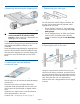

13b Connecting a SAS autoloader
SAS signal rates require clean connections with a
minimum number of connections between the HBA
and the autoloader. Do not use adapters or converters
between the HBA and the autoloader. HP recommends
a maximum SAS cable length of six meters.
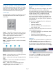
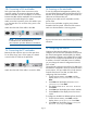
Attach a mini-SAS connector on the SAS cable to port
A on the tape drive. For an LTO-6 drive, port A is the
upper port.
Attach the other end of the cable to the HBA.
NOTE: If you are connecting the autoloader
to a Blade Server, the Blade Server
documentation provides additional information.
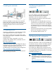
13c Connecting the FC autoloader
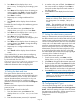
Remove the dust cap from port A on the tape drive.
For an LTO-6 drive, port A is the upper port. Attach
one end of the FC cable to the tape drive.
Attach the other end of the cable to a switch or HBA.
14 Powering on the autoloader
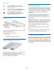
To use the web-based management interface, plug
one end of the Ethernet cable into the Ethernet port on
the back of the autoloader. Plug the other end of the
cable into an Ethernet LAN port.
Plug the power cable into the autoloader and the
power outlet.
Power on the autoloader using the power button
located on the front panel. Check the LCD screen to
make sure the autoloader is receiving power.
Power on the host server and all devices you powered
off earlier.
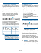
15 Configuring the network
Configuring the network enables you to monitor,
configure, and control most autoloader functions from
the remote management interface (RMI). By default,
the autoloader will obtain an IP address from a DHCP
server. You can configure the autoloader to use a static
IP address. Once the autoloader has an IP address,
you can change the network configuration from the
OCP or RMI.
The autoloader supports IPv4 and IPv6. By default, the
autoloader is configured to use IPv4, the most common
current version. You can enable IPv6 or both Internet
Protocols from the OCP or RMI, and then finish
configuring IPv6 from the RMI.
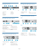
1. From the Home screen, press Next until the
display shows Status/Information. Press
Enter.
2. Press Next until the display shows Network
Information. Press Enter.
3. The display shows IPv4 Network Enabled.
Press Enter.
4. Press Next until the display shows the IP address.
5. Press Cancel until the display shows the Home
screen.
To configure or disable IPv4 addressing from the OCP:
1. From the Home screen, press Next until the
display shows Configuration. Press Enter.
2. Press Next until the display shows Configure
Network Settings. Press Enter.
Page 9