HP StorageWorks XP10000 Disk Array Site Preparation Guide Part number: AE102-96014 Seventh edition: March 2008
Legal and notice information © Copyright 2005, 2008 Hewlett-Packard Development Company, L.P., all rights reserved. Confidential computer software. Valid license from HP required for possession, use or copying. Consistent with FAR 12.211 and 12.212, Commercial Computer Software, Computer Software Documentation, and Technical Data for Commercial Items are licensed to the U.S. Government under vendor's standard commercial license. The information contained herein is subject to change without notice.
Contents About this guide ................................................................................... 7 Intended audience ...................................................................................................................... 7 Related documentation ................................................................................................................ 7 Document conventions and symbols ...........................................................................................
Primary rack dimensions and cable cutout location ........................................................... Primary and secondary rack dimensions and cutout locations ............................................ Calculating clearances ................................................................................................. Environmental requirements ........................................................................................................ Altitude specifications .....................
Figures 1 Fully configured XP10000 rack assembly ................................................................... 18 2 Primary rack dimensions .......................................................................................... 27 3 Primary and secondary rack dimensions and cutouts ................................................... 28 4 Primary rack clearance requirements ......................................................................... 29 5 Power connections for the primary rack .........
Tables 1 Document conventions ............................................................................................... 7 2 Rack dimensions and weights ................................................................................... 19 3 Component weights ................................................................................................ 19 4 Required clearances for primary racks by floor loading and available front clearance ......
About this guide This guide provides information to help you prepare your site for installation of the HP StorageWorks XP10000 Disk Array. Unless otherwise noted, the term disk array in this guide refers to the HP StorageWorks XP10000 Disk Array.
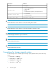
Convention Element Italic text Text emphasis • File and directory names • System output Monospace text • Code • Commands, their arguments, and argument values Monospace, italic Monospace, bold text text • Code variables • Command variables Monospace, bold text WARNING! Indicates that failure to follow directions could result in bodily harm or death. CAUTION: Indicates that failure to follow directions could result in damage to equipment or data.
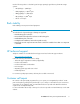
Use the following values to calculate logical storage capacity (logical devices) for HP XP storage systems: • 1 KB (kilobyte) = 1,024 bytes • 1 MB (megabyte) = 1,0242 bytes • 1 GB (gigabyte) = 1,0243 bytes • 1 TB (terabyte) = 1,0244 bytes • 1 block = 512 bytes Rack stability Rack stability protects personnel and equipment. WARNING! To reduce the risk of personal injury or damage to equipment: • Extend leveling jacks to the floor. • Ensure that the full weight of the rack rests on the leveling jacks.
http://www.hp.com/go/selfrepair This product has no customer replaceable components. Product warranties For information about HP StorageWorks product warranties, see the warranty information website: http://www.hp.com/go/storagewarranty Subscription service HP strongly recommends that customers register online using the Subscriber's Choice website: http://www.hp.
1 Site preparation team and tasks The objective of a site preparation is to prepare your site for the successful and timely installation of this HP product. Proper site preparation is vital for the reliability of the disk array. Site preparation involves a careful balance of equipment design criteria, site environmental variables, your business needs, and your budget constraints. In addition to this guide, other site preparation resources may be available to you.
2. Carefully review chapter 2 to understand the site requirements for the disk array. If you plan to connect additional external storage, be sure to take the requirements of that storage into account. See the documentation for the external system. 3. Use the information, instructions, and tools in chapter 2 to determine site requirements for the specific disk array components you ordered. 4. On the site preparation checklist, answer each item Yes or No as it relates to your site.
* Check items Yes No Reference Has a new floor plan been developed to include the new array? The space planning process, page 25 * Does the new floor plan include adequate space for airflow and servicing needs? Floor clearance and cutout requirements, page 26 * Does the new floor plan include the clearance required for the floor's load rating? Floor clearance and cutout requirements, page 26 * Is the computer room structurally complete (walls, floor, air conditioning system, and so on)? * Is t
* Check items * Are sufficient AC outlets, on different lines, available for the equipment? Electrical requirements, page 37 * Does the input voltage correspond to the equipment specifications? Electrical requirements, page 37 * Are the input circuit breakers adequate for equipment loads? Electrical requirements, page 37 * Does the input frequency correspond to equipment specifications? Electrical requirements, page 37 Is an appropriate uninterruptible power supply (UPS) strategy in place? Un
• Placing an order for data communication equipment, including any equipment needed for the Internet-based remote support option The time between placing an equipment order and actual delivery can vary. Contact your HP representative to determine the best estimated delivery dates.
Site preparation team and tasks
2 Site requirements for the XP10000 disk array Your site must meet the requirements described in this chapter before HP can deliver and install the system.
1. Front view of open XP10000 racks 2. Controller with power supplies, control panel, modules, and SVP 3. R0 disk chassis, containing up to 60 drives 4. R1 disk chassis, containing up to 60 drives 5. Primary rack 6. Second rack 7. R2 disk chassis, containing up to 60 drives 8.
You can add more disk chassis in the order shown in Figure 1: R0 (#3), R1 (#4), R2 (#7), and R3 (#8). Your HP support representative can add disk chassis and disk drives online without interruptions to applications or hosts. Additional details about each rack follow. Primary rack expansion In addition to the basic disk chassis (R0), you can expand the disk array in the primary rack as follows: • Add one 60-disk chassis (R1) to the top space of the primary rack (#4). This provides a total of 120 drives.
Product Description kg lb AE010A HP XP12000/10000 32-port 4-Gbps FC SW CHIP 5.9 13 AE011A HP XP12000/10000 32-port 4-Gbps FC LW CHIP 0.02 0.04 AE013A HP XP12000/10000 8-Port FICON SW CHIP 5.7 12.6 AE014A HP XP12000/10000 8-Port FICON LW CHIP 5.7 12.6 AE015A HP XP12000/10000 16-port 2-Gbps FICON SW CHIP 5.9 13 AE016A HP XP12000/10000 16-port 2-Gbps FICON LW CHIP 5.9 13 AE017A HP XP12000/10000 16-Port EXSA CHIP 5.4 11.9 AE018A HP XP12000/10000 8-Port 1-Gbps NAS SW CHIP 6.
Product Description kg lb AE122AS HP XP10000 146-GB 15k-rpm Spare Disk 1 2.2 AE123B HP XP10000 300-GB 10k-rpm Array Group 4 8.8 AE123BS HP XP10000 300-GB 10k-rpm Spare Disk 1 2.2 AE128A HP XP10000 300-GB 15k-rpm Array Group 4 8.8 AE128AS HP XP10000 300-GB 15k-rpm Spare Disk 1 2.2 AE125A HP XP10000 400GB 10k rpm Array Group-4 disks 4 8.8 AE125AS HP XP10000 400GB 10k rpm Spare Disk 1 2.
Part Number Description Weight Quantity Total weight Total weight of your configuration Weight calculation example Weight Quantity Total weight 740 x 1= 740.0 HP XP12000/10000 32-Port 2-Gbps FC CHIP 12.8 x 1= 12.8 AE025A HP XP12000/10000 4-GB Cache Memory 0.44 x 1= 0.4 AE030A HP XP12000/10000 1-GB Shared Memory 0.13 x 3= 0.4 AE104B HP XP10000 Disk Chassis (holds up to 60 drives) 177.0 x 1= 177.0 AE105B HP XP10000 16-Port FC SW CHIP 8-Port ACP 11.0 x 1= 11.
CAUTION: Make sure all floors, stairs, and elevators you use when moving the disk array to the computer room can support the weight and size of the equipment. Failure to do so could damage the equipment or your site. General computer room requirements The goal of a computer room is to maintain an ideal environment for computer equipment, including this system. Make sure your computer room adheres to all national and local building codes for a data center/computer room environment.
Safety requirements When making decisions concerning site safety, your first concern should be the safety of your personnel and then the safety of your equipment. Fundamental safeguards for disk arrays should include a site well away from any sources of potential damage. If you have any questions on site safety, consult your HP representative, your insurance carrier, and local building inspectors for safety recommendations.
The space planning process 1. Document your computer room's existing floor plan, including locations of these items: a. Immovable objects, such as structural support columns b. Walls c. All equipment, furniture, cabinets, racks, data communication equipment, and systems d. Floor cutouts e. Electrical outlets f. Connecting cables and power cords, including lengths g. Floor vents 2.
• Use a raised floor system (254 to 305 mm, 10 to 12 inches) for the most favorable room air distribution system. • Grid panels must be at least 450 x 450 mm (17.72 x 17.72 in). • The floor must have a load rating between 300 and 500 kg per square meter (553 to 921.7 lb per square yard, or 61.4 to 102.4 lb per square foot). The maximum floor loading at any point is 500 kg (1102.3 lb).
Primary rack dimensions and cable cutout location Figure 2 shows dimensions, clearances, and the cable cutout location for the primary rack. The cutout may be off-center as long as it is within the area shown and corresponds to the opening in the bottom of the rack to allow cables to pass through. See the following pages for additional notes. Figure 2 Primary rack dimensions Primary and secondary rack dimensions and cutout locations Figure 3 shows floor clearance dimensions when two racks are installed.
Figure 3 Primary and secondary rack dimensions and cutouts Calculating clearances The total floor space required for the XP10000 disk array includes: • The actual space required by the equipment. • Service clearance — the floor space required to access the disk array. Never use this space for storage. • Additional space required to properly distribute the equipment weight on your computer room floor.
Figure 4 Primary rack clearance requirements The letters a, b, and c in Figure 4 refer to the following: • Clearance a is the space between the service clearance at the left side of the array (100 mm minimum for installing the kick plate) and any other object, such as a desk or wall. • Clearance b is the space between the service clearance at the right side of the array (100 mm for the kick plate) and any other object.
2. In Table 4, find the column for c that most closely matches your value. If your c value is between two table values, use the larger value. Then, find the row for your floor load rating. Where the column and row intersect is the a+b value. Table 4 Required clearances for primary racks by floor loading and available front clearance Floor load rating (kg/m2) Required clearance (a + b) mm Front clearance (c) mm c=0 c = 200 c = 400 c = 600 c = 1000 500 100 0.00 0.00 0.00 0.
• Clearance between racks must be at least 10 mm. If the kick plate is installed after rack placement, allow 100 mm. Table 5 Required clearances for two racks by floor load rating and available front clearance Floorload rating (kg/m2) Required clearance (a + b) mm Front clearance (c) mm c=0 c = 200 c = 400 c = 600 c = 1000 500 0.00 0.00 0.00 0.00 0.00 450 200 100 0.00 0.00 0.00 400 500 300 200 100 0.
Temperature range type Nonoperating temperature range Range –10 to +43 degrees C 14 to 109 degrees F Shipping and storage temperature (product packed in factory packing) –25 to +60 degrees C Temperature shock immunity (maximum rate of temperature change) 10 degrees C per hour –13 to +140 degrees F 18 degrees F per hour Humidity specifications Maintain proper humidity levels. High humidity levels cause galvanic actions to occur between some dissimilar metals.
specifications apply to all three axes. For vibration testing methods, see ASTM D999-91 Standard Methods for Vibration Testing of Shipping Containers. Table 8 Mechanical vibration specifications Condition Specification 0.25 mm, 5–10 Hz Operating 0.05 G, 10–300 Hz 2.5 mm, 5–10 Hz 0.5 G, 10–70 Hz Nonoperating 0.05 mm, 70–99 Hz 1.0 G, 99–300 Hz Shipping and storage (product packed in factory packing) 0.
Table 11 shows the air flow requirements for the frames and disk chassis. Table 11 Air flow specifications Product No. Description Air flow in cubic meters per minute AE102A HP XP10000 Disk Control Frame - DKC 15 AE104B HP XP10000 Disk Chassis 8 AE115B HP XP10000 Disk Array Frame 8 Table 12 presents the power requirements and heat dissipation of individual components. Table 12 Component heat dissipation and power requirements Product No.
Product No. Description Heat output (kW) Power consumption (kVA) AE102A HP XP10000 Disk Control Frame - DKC 0.738 0.761 AE104B HP XP10000 Disk Chassis 0.100 0.103 AE105B HP XP10000 16-Port FC SW CHIP 8-Port ACP 0.370 0.381 AE106A HP XP10000 4Gb CHIP/ACP Combo Board 0.380 0.392 AE110B HP XP10000 Battery 0.044 0.045 AE115B HP XP10000 Disk Array Frame 0.100 0.103 AE120A HP XP10000 73-GB 15k-rpm Array Group 0.088 0.096 AE121A HP XP10000 146-GB 10k-rpm Array Group 0.092 0.
Mechanical filters on the disk array protect it by trapping large dust particles. Smaller particles can pass through some filters, and can eventually cause problems in mechanical parts. Prevent small dust particles from entering the computer room by maintaining its air conditioning system at a high static air pressure level. Your HP representative can help you determine if you need to be concerned about airborne contaminants.
Item Description A public voice phone line near the disk array Needed to allow your staff and HP representatives to communicate inside and outside your site. HP StorageWorks XP Continuous Track (C-Track) The HP StorageWorks XP Continuous Track (C-Track) remote support solution detects and reports system problems to the HP Storage Technology Centers (STCs). C-Track transmits heartbeats, system information messages (SIMs), and configuration information for remote data collection and monitoring purposes.
Safety and dedicated ground The primary reason for grounding electrical systems is safety. The safety ground is required by the National Electric Code (USA) and most other local, regional, and national codes. In addition to safety ground, HP requires that a dedicated (earth reference) ground be installed as a common reference point for all system components. Consult with an HP representative and your electrician to ensure that your electrical system meets all local and national safety codes.
Power line transients Heavy electrical loads from nearby machinery or equipment (for example, elevators or electric welders) can cause intermittent system problems with sophisticated electronic equipment, even if that equipment is on a separate circuit breaker. When faced with these conditions, provide a separate, completely independent power panel with an isolated ground and circuit breaker coming directly from the main building power source or secondary power source.
Site requirements for the XP10000 disk array
3 Electrical specifications for the XP10000 disk array The detailed electrical specifications in this chapter are provided to help your site electrician perform any necessary electrical work related to site preparation. AC line voltage requirements The AC power requirements are essentially the same for both the primary and the second racks. Each rack operates on 200 VAC nominal, 20 amps, 50 or 60 Hz, single-phase power.
Figure 5 Power connections for the primary rack CAUTION: The four PDU outlets (not all shown) are for internal power connections to the disk array only. Do not connect any other equipment to these outlets. Using the outlets for any equipment other than the disk array may compromise disk array reliability or availability. The second rack, shown in Figure 6, has four connections to AC power. Power requirements are 200 VAC, single-phase, 20-Amps.
• • • • • • • HP HP HP HP HP HP HP 4.5 m power cord with stripped ends 240 V power cord w/ IEC 309 plug, 4.5 m 240 V power cord w/ CEE7/7, 4.5 m power cord for China power cord for Israel power cord, 4.5 m, C19/C20 Plug (jumper for UPS) power cord w/IEC 320-C20 connector and 2.5 m jumper for UPS You can supply your own power cables as long as they meet a 20 amp rating, fit the IEC320-C20 PDU inlets, and meet local codes.
European branch circuit requirements To protect the disk array, your building must be wired correctly. Each supply (“hot”) conductor must be protected by a short-circuit protective device and by an overcurrent protective device. Table 15 on page 41 specifies the overcurrent protective devices required for single-phase operation. All protective devices must comply with national standards of the country where the units are to be installed.
4 Delivery and unpacking The disk array equipment is shipped directly from HP. If the disk array is part of a system order, HP coordinates shipment from all HP locations so that all of the equipment arrives at your site at approximately the same time. When your equipment ships, HP communicates the carrier information and an expected delivery date. Factors beyond HP control can cause delivery delays.
Required tools • Claw hammer (if full packaging with wooden crate) • Ratchet wrench or box-open end wrench sizes 11mm (7/16") and 19mm (3/4"), or adjustable end wrench • 6mm hex wrench • Scissors or box knife to cut polyester banding • Safety glasses • Short stepladder (helpful, but not required) Packaging configurations Racks are shipped in one of three standard packaging configurations: • Environmental pack — consists of stretch wrap over corner protectors.
CAUTION: Any movement of the equipment by forklift should be done prior to unpacking. The carton assembly provides the most secure support of the equipment during movement. Transporting the equipment by forklift after the packaging carton has been removed is not advisable. CAUTION: The equipment racks are top heavy and contain very sensitive electronic and mechanical components.
below for key packaging points. Steps 2 through 5 refer to Figure 8. Steps 6 through 8 refer to Figure 9. 1. If shipped in a wooden crate: a. Using an 11mm (7/16") ratchet or wrench, remove the six lag screws at the base of the crate. b. Using the claw end of a claw hammer, remove the crate clamps, and then remove the crate panels. WARNING! Crate clamps are under tension. Wear safety glasses and hold onto the clamp with your free hand during removal. 1. Polyester bands 2. Pallet nails 3.
3. Remove the nails attaching the carton to the pallet. 4. Remove the plastic carton fasteners. 5. Remove the carton. 4. Accessory boxes 5. Ramp 6. Corner pads 7. Poly bag Figure 9 Removing the inner packaging 6. Remove the accessory boxes, ramp, and corner pads. 7. Using a 6mm hex and 19mm wrench, remove the adapter plates that anchor the cabinet to the pallet. 8. Remove the poly bag covering the cabinet. 9.
Delivery and unpacking
Glossary ACP Array control processor. On some HP XP models, such as the HP XP12000, the ACP handles the passing of data between the cache and the physical drives. On other HP XP models, such as the HP XP10000 disk array, this function is handled by the disk adapter on the MIX board. AL Arbitrated loop. AL-PA Arbitrated loop physical address. allocation The ratio of allocated storage capacity versus total capacity as a percentage.
channel processor (CHP) The processors located on the channel adapter (CHA). Synonymous with CHIP. command device A volume on the disk array that accepts Continuous Access or Business Copy control operations which are then executed by the disk array. control unit To organize the storage space attached to the DKC, you can group similarly configured logical devices (LDEVs) with unique control unit images (CUs). CUs are numbered sequentially.
FC-AL Fibre Channel arbitrated loop. FCP Fibre Channel Protocol. fence level A level for selecting rejection of a write I/O request from the host according to the condition of mirroring consistency. FICON IBM mainframe Fiber Optic Connection. GB Gigabytes. GLM Gigabyte link module. HA High availability. HBA Host bus adapter. A built-in function or a card installed in a PC or other host computer to enable connection of the host to the SAN.
mirroring consistency The consistency (usability) of data in a volume (for example, S-VOL). mm Millimeters. MR Magnetoresistive. ms, msec Milliseconds. mutual hot standby system Two servers that are poised to cover for each other if necessary. NAS Network attached storage. node Logically speaking, an environment where instances can be executed. Physically, a processor, which is an element of a cluster system. NVS Nonvolatile storage. OFC Open Fibre Control. OLM Optical link module.
RAID level A RAID Level is one of the ways that disk drives are grouped together to improve performance, data availability/reliability or both. RAID levels are defined from RAID0 to RAID6. HP StorageWorks Disk Arrays in the XP product family support RAID1, RAID5 and RAID6. Not all of these RAID levels are supported by all XP family members. Consult the owner's guide or your HP representative for the details of which RAID levels are supported by your specific XP disk array. RAM Random access memory.
Glossary
Index AC plugs, 42 power, 41 AC cabling European, 43 North American, 43 acoustics, 35 additional components, 19 air conditioning, 31 and metallic particulate contamination, 36 dust control, 36 air pressure, 23, 31, 36 airborne contaminants, 35 altitude, 31 antistatic carpeting, 26 containers, 23 floor wax, 23 flooring, 23 furniture, 23 audience, 7 clearances, 26 components, additional, 19 computer room air pressure, 23 data communication requirements, 36 electrical requirements, 37 environmental requireme
disk array acoustic specifications, 35 basic configuration, 17 delivery of, 45 dimensions, 19 electrical specifications, 41 heat dissipation, 33 humidity specifications, 32 power connections, 38, 41 power consumption, 33 primary rack, 17 second rack, 17 unpacking, 45 vibration specifications, 32 disk chassis, 17 disk controller, 17 document related documentation, 7 document conventions, 7 documentation HP website, 7 providing feedback, 10 dust control, 35 G grid panels, floor, 26 grounding, 38, 38, 44 H
North American AC power cabling, 43 O operating voltages, 41 P particulate contamination, metallic, 36 phone line, 36 physical specifications, 17 plugs AC, 42 pollution control, 35 power requirements, 37 AC connections, 41 cables, 42 consumption, 33 cords, 41, 42 UPS, 39 power cabling European, 43 North American, 43 power cords floor cutouts for, 26 power line transients, 39 primary rack, 17, 19 R rack stability warning, 9 racks, 19 described, 17 raised floor, 24 See also floor, 25 receptacles, 38 relate
websites, 7 customer self repair, 9 HP, 10 HP Subscriber's choice, 10 weights, 19, 19 calculating, 21 wet bulb temperature, 32 windows, in the computer room, 23 X XP Continuous Track, 37 60