HP StorageWorks XP10000 Disk Array Owner's Guide Part number: AE102-96013 Seventh edition: March 2008
Legal and notice information © Copyright 2005, 2008 Hewlett-Packard Development Company, L.P., all rights reserved. Confidential computer software. Valid license from HP required for possession, use or copying. Consistent with FAR 12.211 and 12.212, Commercial Computer Software, Computer Software Documentation, and Technical Data for Commercial Items are licensed to the U.S. Government under vendor's standard commercial license. The information contained herein is subject to change without notice.
Contents About this guide ................................................................................... 7 Intended audience ...................................................................................................................... 7 Related documentation ................................................................................................................ 7 Document conventions and symbols ...........................................................................................
Optional management server ..................................................................................................... 25 3 HP XP10000 operations ................................................................... 27 General safety guidelines .......................................................................................................... Powering down the disk array .................................................................................................... Emergency power off .
Figures 1 HP XP10000 Disk Array configuration ....................................................................... 13 2 HP XP10000 control panel components ..................................................................... 22 3 Backup power sequence .......................................................................................... 25 4 Optional HP StorageWorks XP Command View Advanced Edition software configuration ...............................................................................
Tables 1 Document conventions ............................................................................................... 7 2 HP XP10000 Disk Array specifications ...................................................................... 15 3 HP XP10000 control panel components ..................................................................... 22 4 Temperature specifications ....................................................................................... 31 5 Humidity specifications ..............
About this guide This guide provides information about owning and operating the HP StorageWorks XP10000 Disk Array. Unless otherwise noted, the term disk array in this guide refers to the HP XP10000 Disk Array.
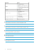
Convention Element • Keys that are pressed • Text typed into a GUI element, such as a box Bold text • GUI elements that are clicked or selected, such as menu and list items, buttons, tabs, and check boxes Italic text Text emphasis • File and directory names • System output Monospace text • Code • Commands, their arguments, and argument values Monospace, italic Monospace, bold text text • Code variables • Command variables Emphasized monospace text WARNING! Indicates that failure to follow direc
Conventions for storage capacity values Use the following values to calculate physical storage capacity (hard disk drives) for HP XP storage systems: • 1 KB (kilobyte) = 1,000 bytes • 1 MB (megabyte) = 1,0002 bytes • 1 GB (gigabyte) = 1,0003 bytes • 1 TB (terabyte) = 1,0004 bytes Use the following values to calculate logical storage capacity (logical devices) for HP XP storage systems: • 1 KB (kilobyte) = 1,024 bytes • 1 MB (megabyte) = 1,0242 bytes • 1 GB (gigabyte) = 1,0243 bytes • 1 TB (terabyte) = 1,024
• Detailed questions For continuous quality improvement, calls may be recorded or monitored. Customer self repair HP customer self repair (CSR) programs allow you to repair your StorageWorks product. If a CSR part needs replacing, HP ships the part directly to you so that you can install it at your convenience. Some parts do not qualify for CSR. Your HP-authorized service provider will determine whether a repair can be accomplished by CSR.
1 Overview of the HP XP10000 Disk Array This disk array is part of the HP StorageWorks XP Disk Array series of high-performance RAID-capable disk array systems used to store large quantities of data in an efficient and secure manner. XP disk arrays support multiple operating systems, platforms, and RAID groups.
the appropriate maintenance activity, without interruption to applications or hosts. For more information, see “HP StorageWorks Continuous Track XP” on page 17.
1. Front of the open HP XP10000 disk array 2. Controller, power supplies, control panel, SVP, disk adapters 3. R0 disk chassis, containing up to 60 disk drives 4. R1 disk chassis, containing up to 60 disk drives 5. Primary rack 6. Second rack 7. R2 disk chassis, containing up to 60 disk drives 8.
2. 3. Add a second rack with one 60-disk chassis (R2, #7 in Figure 1), providing a total of up to 180 drives. Add a second 60-disk chassis (R3, #8 in Figure 1) to the second rack for a total of up to 240 drives. An HP support representative is required to add disk chassis and disk drives. Disk chassis and disk drives can be added online without interruption to applications or hosts.
• • • • • • • HP RAID Manager Library software Site preparation services Installation and configuration services Proactive monitoring and support Reactive hardware support Software support Documentation CD including this owner's guide, configuration guides for host operating systems, and software guides *The product is also available without a disk chassis.
Feature Specification Maximum hard disk drives 120 in one rack, 240 in two racks Maximum spare disk drives 16 Maximum parity groups/array 59 Maximum disk drive capacity 69.
• • • • Nonstop VMware z/OS Mainframe For the latest information on supported operating systems and versions, contact your HP support representative or visit the HP website: http://www.hp.
• Simplify disaster recovery • Improve data security The following topics summarize the types of available software. To learn about specific XP software products, visit the HP website and navigate to XP storage software: http://www.hp.com Storage management software HP includes versatile Java-based management software with the XP disk array and offers a range of additional management tools.
• • • • HP HP HP HP StorageWorks StorageWorks StorageWorks StorageWorks XP XP XP XP Continuous Access Journal Software RAID Manager Replication Monitor Software Cluster Extension Software Mainframe software HP offers a wide range of mainframe software, including disaster recovery applications, point-in-time copy solutions, backup applications, and migration solutions.
Overview of the HP XP10000 Disk Array
2 HP XP10000 hardware components There are no single points of failure in HP XP10000 disk arrays. Redundant logic assemblies, controllers, disk drives, and power supplies can be removed or replaced without interrupting access to data. This section describes individual physical components of the disk array. See Figure 1 on page 13 for an overview of the disk array hardware. CAUTION: Only your HP support representative can remove or replace hardware.
Figure 2 HP XP10000 control panel components Table 3 HP XP10000 control panel components Item Label Indicator Description During normal operation, this LED should be on. 1 READY LED (Green) ON: Input/output on the channel interface is enabled. OFF: The system is not accepting data. During normal operation, this LED should be off. ON: One or more of the following: The DC is under voltage. The DC is over current. The temperature is abnormally high.
Item Label Indicator Description During normal operation, this LED should be off. 3 MESSAGE LED (Amber) ON: A service information message (SIM) has been issued from either storage cluster. If the disk array is set up for remote support, your HP support representative is notified automatically. If the disk array is not set up with remote support, place a service call to HP to have the message evaluated to determine if any action is required. BLINKING: An SVP failure has occurred.
Item Label Indicator Description During normal operation, this LED should be on. 7 BS-ON LED (Amber) ON: The disk array is plugged in and receiving power from the primary AC outlet. The SVP is receiving power from the outlet. OFF: The disk array is not receiving power from the primary AC outlet. Check the electrical outlets in your building. During normal operation, this LED should be on. 8 PS-ON LED (Green) ON: The PS ON/OFF switch is on.
The disk array must contain at least one spare disk drive and can contain up to 16. Any of the spare disk drives can back up any other disk drive of equal rotational speed and equal or lesser capacity, in any disk chassis, even if the failed disk and the spare disk are in different array domains. The XP10000 disk array supports 73 GB, 146 GB, 300 GB and 400 GB Fibre Channel disk drives.
1. Command View XP Advanced Edition server 2. Ethernet LAN connection 3.
3 HP XP10000 operations During normal operations, the disk array does not require intervention and you should not attempt to open the disk array cabinets. The disk array reports any service information messages (SIMs) to the SVP and the Device Manager server. If the array is set up for remote support, the SVP automatically reports SIMs to the HP Storage Technology Center (STC). For more information on SIMs, see “Service information messages” on page 33.
CAUTION: Do not perform any procedures not described in this guide. If you have any questions or concerns, contact your HP support representative. WARNING! Do not touch areas marked HAZARDOUS, even with the power off. These areas contain high-voltage power. CAUTION: If you detect any abnormal noise, smell, or smoke coming from the disk array, immediately power off the disk array by following the emergency power off procedure later in this chapter.
Emergency power off The system does not have an emergency power off switch. In an emergency when it is crucial to power off the system immediately for safety reasons, remove power at the AC branch circuit breakers in your facility that supply power to the system. Take care when placing these breakers that they are clearly marked and easily accessible. CAUTION: Performing an emergency power off immediately shuts down the system, neglecting the normal power off sequence.
Manual restart after power is restored CAUTION: After power is restored to your site and before restoring power to the system, HP recommends that you have an electrician verify the power to ensure that all phases are restored and input power is stable. Before you power on the system, power on any external disk array(s) first and make sure they are operating properly. For assistance recovering from a power outage, contact your HP support representative. To restart the disk array manually: 1.
PS-ON turns green. MESSAGE LED may turn amber if the system is not configured for remote support, signifying a SIM was generated because the system lost power unexpectedly. READY LED turns green, signifying the system is ready. CAUTION: Powering on the disk array can take several minutes. Power on is complete only when the READY LED turns green. Operating specifications This section provides some general specifications.
Humidity range type Non-condensing relative humidity (RH) Non-operating maximum wet bulb temperature 27 degrees C (81 F) Shipping and storage maximum wet bulb temperature 29 degrees C (84 F) Mechanical vibration Continuous vibration can cause a slow degradation of mechanical parts and, when severe, can cause data errors in disk drives. Mechanical connections such as printed circuit assembly (PCA) conductors, cable connectors, and processor backplane wiring can also be affected by vibrations.
4 HP XP10000 Troubleshooting Service information messages The system generates service information messages (SIMs) to identify normal operations, service requirements, and failures. SIMs are generated by the SVP and the system microprocessors. Your HP support representative uses the SIMs to monitor and troubleshoot the system. You can view SIMs using the system's management software.
Item 5 34 Description If the system is set up for remote support, HP XP Continuous Track reports the SIMs to STC through a dedicated dialup connection.SIMs are classified according to severity: service, moderate, serious, or acute. Service and moderate levels do not require immediate attention and are addressed during routine maintenance. These failures are often corrected before the failure becomes apparent.
5 Regulatory statements FCC EMC statement (USA) This equipment has been tested and found to comply with the limits for a Class A digital device, pursuant to Part 15 of the FCC rules. These limits are designed to provide reasonable protection against harmful interference when the equipment is operated in a commercial environment.
VCCI EMC statement (Japan) BSMI EMC statement (Taiwan) RRL EMC statement (Korea) Harmonics conformance (Japan) German noise declaration XP10000: Schalldruckpegel Lp = 70 dB(A) Am Arbeitsplatz (operator position) Normaler Betrieb (normal operation) Nach ISO 7779:1988 / EN 27779:1991 (Typprüfung) Laser safety When equipped with native Fibre Channel adapters, this product contains a laser internal to the Optical Link Module (OLM) contained on the 8-port Fibre Channel Adapter board and 8-port FICON 36 Re
board, and on the 16-port Fibre Channel Adapter board and 16-port FICON board for connection to a fibre communications network. In the USA, the OLM is certified as a Class 1 laser product conforming to the PRT requirements contained in the Department of Health and Human Services (DHHS) regulation 21 CFR, Subchapter J. The certification is indicated by a label on the plastic OLM housing.
Dutch English Estonian 38 Regulatory statements
Finnish French German XP10000 Disk Array Owner's Guide 39
Greek Hungarian Italian 40 Regulatory statements
Latvian Lithuanian Polish XP10000 Disk Array Owner's Guide 41
Portuguese Slovak Slovenian 42 Regulatory statements
Spanish Swedish XP10000 Disk Array Owner's Guide 43
Regulatory statements
Glossary ACP Array control processor. On some XP models, such as the XP12000, the ACP handles the passing of data between the cache and the physical drives. On other XP models, such as the HP XP10000, this function is handled by the disk adapter on the MIX board. AL Arbitrated loop. AL-PA Arbitrated loop physical address. allocation The ratio of allocated storage capacity versus total capacity as a percentage. “Allocated storage” refers to those LDEVs that have paths assigned to them.
channel processor (CHP) The processors located on the channel adapter (CHA). Synonymous with CHIP. command device A volume on the disk array that accepts Continuous Access or Business Copy control operations which are then executed by the disk array. control unit To organize the storage space attached to the DKC, you can group similarly configured logical devices (LDEVs) with unique control unit images (CUs). CUs are numbered sequentially.
FC-AL Fibre Channel arbitrated loop. FCP Fibre Channel Protocol. fence level A level for selecting rejection of a write I/O request from the host according to the condition of mirroring consistency. FICON IBM mainframe Fiber Optic Connection. GB Gigabytes. GLM Gigabyte link module. HA High availability. HBA Host bus adapter. A built-in function or a card installed in a PC or other host computer to enable connection of the host to the SAN.
mirroring consistency The consistency (usability) of data in a volume (for example, S-VOL). mm Millimeters. MR Magnetoresistive. ms, msec Milliseconds. mutual hot standby system Two servers that are poised to cover for each other if necessary. NAS Network attached storage. node Logically speaking, an environment where instances can be executed. Physically, a processor, which is an element of a cluster system. NVS Nonvolatile storage. OFC Open Fibre Control. OLM Optical link module.
RAID group See “array group.” RAID level A RAID Level is one of the ways that disk drives are grouped together to improve performance, data availability/reliability or both. RAID levels are defined from RAID0 to RAID6. HP StorageWorks Disk Arrays in the XP product family support RAID1, RAID5 and RAID6. Not all of these RAID levels are supported by all XP family members. Consult the owner's guide or your HP representative for the details of which RAID levels are supported by your specific XP disk array.
Glossary
Index A AC power, 32 array management, 17 audience, 7 automatic restart, 30 B batteries, backup, 25, 29 C cables mechanical vibration, 32 cache battery backup, 25 Command View XP Advanced Edition Software, 17, 25 components hardware, 21 included, 14 optional, 15 required additional, 15 connectivity, 12 control panel, 21 conventions document, 7 storage capacity values, 9 text symbols, 8 customer self repair, 10 D data availability, 11 data integrity, 14 data protection and recovery software, 19 disk array
H R hardware control panel, 21 disk array frame, 24 disk control frame, 21 disk drives, 24 features, 14 management server, 25 normal operations, 27 physical components, 21 RAID options, 15 service processor. See SVP, 21 specifications, 16, 31 hazard warnings, 27 help obtaining, 9 high availability, 14 HP technical support, 9 HP Storage Technology Center.
W warning hazard, 27 rack stability, 9 websites customer self repair, 10 HP, 10 HP Subscriber's Choice for Business, 10 product manuals, 7 wet bulb temperature, 31 X XP Continuous Track, 11, 14, 17, 34 XP10000 Disk Array Owner's Guide 53