HP XP P9000 RAID Manager Installation and Configuration Guide Abstract This guide describes and provides instructions to install and configure HP XP P9000 RAID Manager Software on HP XP P9500 disk arrays. The intended audience is a storage system administrator or authorized service provider with independent knowledge of HP XP P9000 disk arrays and the HP Remote Web Console.
© Copyright 2010, 2014 Hewlett-Packard Development Company, L.P. Confidential computer software. Valid license from HP required for possession, use or copying. Consistent with FAR 12.211 and 12.212, Commercial Computer Software, Computer Software Documentation, and Technical Data for Commercial Items are licensed to the U.S. Government under vendor's standard commercial license. The information contained herein is subject to change without notice.
Contents 1 Installation requirements..............................................................................5 System requirements..................................................................................................................5 Supported environments............................................................................................................7 Supported Business Copy environments...................................................................................
5 Troubleshooting........................................................................................47 Troubleshooting......................................................................................................................47 6 Support and other resources......................................................................48 Contacting HP........................................................................................................................48 Subscription service.........
1 Installation requirements This chapter describes the installation requirements for the RAID Manager (RAID Manager) software. System requirements RAID Manager operations involve the RAID Manager software on the UNIX/PC server host, the command device(s) on the RAID storage system(s), and the logical volumes on the RAID storage system(s). The system requirements for RAID Manager are: • RAID Manager software product. The RAID Manager software is supplied on CD-ROM or diskette.
the description of the configuration file.It is necessity (Number of units ID×200 KB + Number of LDEV×360B + Number of the entry×180B) in the minimum ◦ Unit ID: the number of the storage chassis ◦ Number of LDEV: the number of the LDEVs (each instance) ◦ Number of entry: the number of the paired entries Example:If 1:3 pair configuration, the primary instance becomes the number of the LDEVs =1 and the number of the entries (the number of the pairs) = 3.
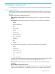
Supported environments This section specifies the supported operating systems, failover software, and I/O interfaces for data management operations using RAID Manager. For the latest information on host software support for RAID Manager, please contact your HP account team. Supported Business Copy environments Table 1 Supported platforms for Business Copy Vendor Operating System Failover Software Volume Manager I/O Interface Oracle Solaris 2.
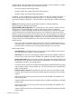
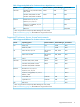
Table 2 Supported platforms for Continuous Access Synchronous (continued) Vendor IBM Operating System Failover Software Volume Manager I/O Interface HP-UX 11.20 or later on IA64* MC/Service Guard LVM, SLVM Fibre Digital UNIX 4.0 TruCluster LSM SCSI Tru64 UNIX 5.0 TruCluster LSM SCSI/Fibre OpenVMS 7.3-1 – – Fibre DYNIX/ptx 4.4 ptx/Custer LVM SCSI/Fibre AIX 4.3 HACMP LVM SCSI/Fibre z/Linux (Suse 8) – – Fibre (FCP) Windows NT 4.
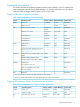
Table 3 Supported platforms for Continuous Access Asynchronous (continued) Vendor Operating System Failover Software Volume Manager I/O Interface Microsoft Windows NT 4.0; Windows 2000, 2003, 2008 MSCS LDM Fibre Windows 2003/2008 on IA641 MSCS LDM Fibre – – SCSI/Fibre2 AS/ES 2.1, 3.0 Update2, 4.0, 5.0 on EM64T / IA641 – – Fibre IRIX64 6.5 – – SCSI/Fibre Windows 2003/2008 on EM64T Red Hat Red Hat Linux 6.0, 7.0, 8.0 AS/ES 2.1, 3.0, 4.0, 5.
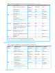
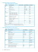
Supported Snapshot environments Table 5 Supported platforms for Snapshot Vendor Operating System Failover Software Volume Manager I/O Interface Sun Solaris 2.8 – VxVM Fibre Solaris 10 /x86 – VxVM Fibre HP-UX 11.0/11.2x – LVM, SLVM Fibre HP-UX 11.2x on IA641 – LVM, SLVM Fibre IBM AIX 5.1 – LVM Fibre Microsoft Windows 2000, 2003, 2008 – LDM Fibre – LDM Fibre – – Fibre** AS/ES 2.1, 3.0 Update 2, 4.0, 5.0 on EM64T / IA64* – – Fibre** Tru64 UNIX 5.
Table 6 Supported Platforms for Data Retention (continued) Vendor Operating System Volume Manager I/O Interface Red Hat Red Hat Linux – SCSI/Fibre2 – Fibre – SCSI/Fibre 6.0/7.0/AS2.1, 3.0, 4.0 AS2.1, 3.0 Update2, 4.0 on IA641 AS 4.0 on EM64T SGI IRIX64 6.5 1. IA64: using IA-32EL on IA64 (except RAID Manager for Linux/IA64) 2. See Troubleshooting described in the HP P9000 RAID Manager User Guide.
Supported guest OS for VM Table 8 VM Vendor Layer Guest OS RAID Manager support confirmation Volume mapping I/O interface Windows 2008 R2 Confirmed - - Windows 2000 Server Unconfirmed RDM* Fibre Windows NT 4.0 Unconfirmed - - RHAS 3.0 Confirmed RDM* Fibre SLES 9.0 Unconfirmed - - Solaris 10 u3 (x86) Confirmed RDM* Fibre SVC Linux Kernel 2.4.9 Confirmed Direct Fibre IBM AIX 5.3 VIO Server *2 Client AIX 5.3 Confirmed Physical mode Fibre Server AIX 5.
Table 10 Supported Platforms: IPv4 vs IPv6 IPv4 RAID Manager / IPv6 HP-UX Solaris AIX Windows Linux Tru64 OpenVMS AV AV AV N/A AV AV N/A AV AV AV N/A AV AV N/A AIX AV AV AV N/A AV AV N/A Windows AV AV AV N/A AV AV N/A Linux AV AV AV N/A AV AV N/A Tru64 AV AV AV N/A AV AV N/A OpenVMS AV AV AV N/A AV AV AV IRIX64 AV AV AV N/A AV AV N/A RAID HP-UX Manager Solaris / IPv4 Legend: AV: Available for communicating with different platforms.
Figure 1 Example of a RAID Manager configuration on z/Linux The restrictions for using RAID Manager with z/Linux are: • Command device. RAID Manager uses a SCSI Path-through driver to access the command device. As such, the command device must be connected through FCP adaptors. • Open Volumes via FCP. You can control the Business Copy and Continuous Access Synchronous pair operations without any restrictions. • Mainframe (3390-9A) Volumes via FICON.
The following commands cannot be used because there is no PORT information: • raidscan -pd , raidar -pd , raidvchkscan -pd • raidscan -find [conf] , mkconf Requirements and restrictions for VM Restrictions for VMware ESX Server Whether RAID Manager (RM) runs or not depends on the support of guest OS by VMware. In addition, the guest OS depends on VMware support of virtual H/W (HBA).
6. About running on SVC. The ESX Server 3.0 SVC (service console) is a limited distribution of Linux based on Red Hat Enterprise Linux 3, Update 6 (RHEL 3 U6). The service console provides an execution environment to monitor and administer the entire ESX Server host. The RAID Manager user can run RAID Manager by installing “RAID Manager for Linux” on SVC.
hdisk2 -> NOT supported INQ. : : hdisk19 -> NOT supported INQ. [AIX ] [VDASD ] [AIX ] [VDASD ] The following commands discover the volumes by issuing SCSI inquiry. These commands cannot be used, because there is no port/LDEV for RAID information. raidscan -pd , raidar -pd , raidvchkscan -pd raidscan -find [conf] , mkconf.sh, inqraid pairxxx -d[g] , raidvchkdsp -d[g] , raidvchkset -d[g] \\.\CMD-Serial#-LDEV#-Port#:/dev/rhdisk on horcm.
3. 4. Lun sharing between guest OS and console OS. It is not possible to share a command device as well as a normal Lun between a guest OS and a console OS. Running RAID Manager on Console OS. The console OS (management OS) is a limited Windows, like Windows 2008 Server Core, and the Windows standard driver is used. Also the console OS provides an execution environment to monitor and administer the entire Hyper-V host.
For Windows systems: Ws2_32.dll For HP-UX (PA/IA) systems: /usr/lib/libc.sl However, RAID Manager may need to specify a different PATH to use the library for IPv6. After this consideration, RAID Manager also supports the following environment variables for specifying a PATH: • $IPV6_DLLPATH (valid for only HP-UX, Windows): This variable is used to change the default PATH for loading the Library for IPv6. For example: export IPV6_DLLPATH=/usr/lib/hpux32/lib.so horcmstart.
where Device:[directory] is defined as SYS$POSIX_ROOT (3) IPC method using MailBox driver As an alternate method of the UNIX domain socket for IPC (Inter Process Communication), RAID Manager use the mailbox driver to enable the communication between RAID Manager and HORCM.
$$ horcmshutdown 0 1 inst 0: HORCM Shutdown inst 0 !!! inst 1: HORCM Shutdown inst 1 !!! $ (5) Command device RAID Manager uses the SCSI class driver for accessing the command device on the XP1024/XP128 Disk Array, because OpenVMS does not provide the raw I/O device such as UNIX, and defines “DG*,DK*,GK*” as the logical name for the device. The SCSI class driver requires the following privileges: DIAGNOSE and PHY_IO or LOG_IO (for details see the OpenVMS manual).
• -CLI or -CLIWP or -CLIWN or -CM for the inqraid options • Environmental variable name such as HORCMINST … controlled by CRTL Also you need to define the following logical name to your login.com in order to distinguish the uppercase and the lowercase: $ DEFINE DECC$ARGV_PARSE_STYLE ENABLE$ SET PROCESS/PARSE_STYLE=EXTENDED (10) Regarding using spawn command You can also start the HORCM process easily by using the spawn command. The following examples used SPAWN command on DCL.
$ PRODUCT INSTALL RM /source=Device:[directory]/LOG _$ /destination=SYS$POSIX_ROOT:[000000] Device:[directory] where HITACHI-ARMVMS-RM-V0122-2-1.PCSI exists : : $ PRODUCT SHOW PRODUCT RM ----------------------------------------- ----------- -----------PRODUCT KIT TYPE STATE ----------------------------------------- ----------- -----------HITACHI ARMVMS RM V1.
After making the S-VOL for Writing enable by using “pairsplit” or “horctakeover” command, you need to perform the “mcr sysman” command in order to use the S-VOLs for backup or disaster recovery.
(5) Verify a physical mapping of the logical device.
Command examples in DCL (1) Setting the environment variable by using Symbol. $ HORCMINST := 0$ HORCC_MRCF := 1 $ raidqry -l No Group Hostname HORCM_ver Uid Serial# Micro_ver Cache(MB) 1 --VMS4 01-22-03/06 0 30009 50-04-00/00 8192 $ $ pairdisplay -g VG01 -fdc Group PairVol(L/R) Device_File M ,Seq#,LDEV#.P/S,Status, % ,P-LDEV# M VG01 oradb1(L) DKA146 0 30009 146..S-VOL PAIR, 100 147 VG01 oradb1(R) DKA147 0 30009 147..P-VOL PAIR, 100 146 VG01 oradb2(L) DKA148 0 30009 148..
DKA146 URA URA_000 CL1-H 0 2 0 30009 146 DKA147 URA URA_001 CL1-H 0 3 0 30009 147 DKA148 URA URA_002 CL1-H 0 4 0 30009 148 DKA149 URA URA_003 CL1-H 0 5 0 30009 149 DKA150 URA URA_004 CL1-H 0 6 0 30009 150 HORCM Shutdown inst 9 !!! Please check 'SYS$SYSROOT:[SYSMGR]HORCM9.CONF','SYS$SYSROOT:[SYSMGR.LOG9.CURLOG] HORCM_*.LOG', and modify 'ip_address & service'. HORCM inst 9 finished successfully. $SYS$SYSROOT:[SYSMGR]horcm9.conf (/sys$sysroot/sysmgr/horcm9.
$1$DGA148 0 F CL2-H $ pairdisplay -g BCVG -fdc Group PairVol(L/R) Device_File M BCVG oradb1(L) $1$DGA146 0 BCVG oradb1(R) $1$DGA147 0 $ $ pairdisplay -dg $1$DGA146 Group PairVol(L/R) (Port#,TID, LU-M) BCVG oradb1(L) (CL1-H , 0, 2-0) BCVG oradb1(R) (CL1-H , 0, 3-0) $ 0 4 30009 148 OPEN-9 ,Seq#,LDEV#..P/S,Status, 30009 146..P-VOL PAIR, 30009 147..S-VOL PAIR, % ,P-LDEV# M 100 147 100 146 - ,Seq#,LDEV#..P/S,Status, Seq#,P-LDEV# M 30009 146..P-VOL PAIR,30009 147 30009 147..
(5) Verify a physical mapping of the logical device. bash$ export HORCMINST=0 bash$ raidscan -pi DKA145-151 -find DEVICE_FILE UID S/F PORT TARG DKA145 0 F CL1-H 0 DKA146 0 F CL1-H 0 DKA147 0 F CL1-H 0 DKA148 0 F CL1-H 0 DKA149 0 F CL1-H 0 DKA150 0 F CL1-H 0 DKA151 0 F CL1-H 0 LUN 1 2 3 4 5 6 7 SERIAL 30009 30009 30009 30009 30009 30009 30009 LDEV 145 146 147 148 149 150 151 PRODUCT_ID OPEN-9-CM OPEN-9 OPEN-9 OPEN-9 OPEN-9 OPEN-9 OPEN-9 (6) Describe the known HORCM_DEV on /etc/horcm*.conf. FOR horcm0.
Using RAID Manager with Hitachi and other storage systems Table 11 (page 30) shows the related two controls between RAID Manager and the RAID storage system type (Hitachi or HP XP). Figure 6 (page 31) shows the relationship between the application, CCI, and RAID storage system.
Figure 6 Relationship between application, CCI, and storage system Using RAID Manager with Hitachi and other storage systems 31
2 Installing and configuring RAID Manager This chapter describes and provides instructions for installing and configuring RAID Manager. Installing the RAID Manager hardware Installation of the hardware required for RAID Manager is performed by the user and the HP representative. To install the hardware required for RAID Manager operations: 1. User: 1. Make sure that the UNIX/PC server hardware and software are properly installed and configured. See “Supported environments” (page 7). 2.
to UNIX commands that may be different on your platform. Please consult your operating system documentation (for example, UNIX man pages) for platform-specific command information. To install the RAID Manager software in the root directory: 1. Insert the installation medium into the I/O device properly. 2. Move to the current root directory: # cd /. 3. Copy all files from the installation medium using the cpio command: 4.
1. 2. 3. 4. 5. Change the owner of the following RAID Manager files from the root user to the desired user name: • /HORCM/etc/horcmgr • All RAID Manager commands in the /HORCM/usr/bin directory • All RAID Manager log directories in the /HORCM/log* directories Change the owner of the raw device file of the HORCM_CMD command device in the configuration definition file from the root user to the desired user name.
Windows installation Make sure to install RAID Manager on all servers involved in RAID Manager operations. If network (TCP/IP) is not established, install a network of Windows attachment, and add TCP/IP protocol. To install the RAID Manager software on a Windows system: 1. Insert the installation medium (for example, CD-ROM) into the proper I/O device. 2. Run Setup.exe (\program\RM\WIN_NT\RMXP\Setup.exe or \program\RM\WIN_NT\RMXP_X64\Setup.
Because the ACL (Access Control List) of the Device Objects is set every time Windows starts-up, the Device Objects are also required when Windows starts-up. The ACL is also required when new Device Objects are created. RAID Manager administrator tasks 1. 2. Establish the HORCM (/etc/horcmgr) startup environment.
2. Execute the following command: $ PRODUCT INSTALL RM /source=Device:[PROGRAM.RM.OVMS]/LOG _$ /destination=SYS$POSIX_ROOT:[000000] Device:[PROGRAM.RM.OVMS] where HITACH-ARMVMS-RM-V0122-2-1.PCSI exists 3. Verify installation of the proper version using the raidqry command: $ raidqry -h Model: RAID-Manager/OpenVMS Ver&Rev: 01-22-03/06 Usage: raidqry [options] 4. Follow the requirements and restrictions in “Porting notice for OpenVMS” (page 19).
Setting up UDP ports This section contains information that may be of assistance in setting up strict firewalls. If you do not have a HORCM_MON IP address in your configuration definition file, RAID Manager (horcm) opens the following ports on horcmstart.
6. To set an alternate command device, repeat this procedure for another volume. For information about alternate command devices, see “About alternate command devices” (page 39). NOTE: • For Solaris operations, the command device must be labeled. • To enable dual pathing of the command device under Solaris systems, include all paths to the command device on a single line in the HORCM_CMD section of the configuration definition file.
available, all commands terminate abnormally, and the host cannot issue RAID Manager commands to the storage system. To ensure that RAID Manager operations continue when a command device becomes unavailable, you should set one or more alternate command devices. Because the use of alternate I/O pathing depends on the platform, restrictions are placed upon it. For example, on HP-UX systems only devices subject to the LVM can use the alternate path PV-LINK.
characteristics. And the RAID storage system determines whether it is a Fast Snap pair or a Snapshot pair based on the type of the pool to be used. There are following sections in the configuration definition file: • HORCM_MON: Defines information about the local host. • HORCM_CMD: Defines information about the command (CMD) devices. • HORCM_DEV or HORCM_LDEV: Defines information about the copy pairs. • HORM_INST: Defines information about the remote host.
Do not edit the configuration definition file while RAID Manager is running. Shut down RAID Manager, edit the configuration file as needed, and then restart RAID Manager. Do not mix pairs created with the “At-Time Split” option (-m grp) and pairs created without this option in the same group defined in the RAID Manager configuration file.
3 Upgrading RAID Manager For upgrading RAID Manager software, the RMuninst script on the CD-ROM is used. For other media, please use the instructions in this chapter to upgrade the RAID Manager software. The instructions may be different on your platform. Please consult your operating system documentation (for example, UNIX man pages) for platform-specific command information.
6. 7. 8. Execute Setup.exe (\program\RM\WIN_NT\RMXP\Setup.exe or \program\RM\WIN_NT\RMXP_X64\Setup.exe on the CD) and follow the instruction on the screen to complete the installation. The install directory is HORCM (fixed value) directly under the drive. An InstallShield opens. Follow the instructions on the screen to install the RAID Manager software. Reboot the Windows server, and verify that the correct version of the RAID Manager software is running on your system by executing the raidqry -h command.
4 Removing RAID Manager This chapter explains how to remove RAID Manager. Removing RAID Manager in a UNIX environment To remove the RAID Manager software: 1. If you are discontinuing local and/or remote copy functions (for example, Business Copy, Continuous Access Synchronous), delete all volume pairs and wait until the volumes are in simplex status. If you will continue copy operations using Remote Web Console, do not delete any volume pairs. 2.
2. You can remove the RAID Manager software only when RAID Manager is not running. If RAID Manager software is running, shut down RAID Manager using the horcmshutdown command to ensure a normal end to all functions: One RAID Manager instance: D:\HORCM\etc> horcmshutdown Two RAID Manager instances: D:\HORCM\etc> horcmshutdown 0 1 3. Delete the RAID Manager software using the Add or Remove Programs control panel: 1. Open the Control Panel, and double-click Add or Remove Programs. 2.
5 Troubleshooting This chapter provides troubleshooting information. Troubleshooting If you have a problem installing or upgrading the RAID Manager software, ensure that all system requirements and restrictions have been met.
6 Support and other resources Contacting HP For worldwide technical support information, see the HP support website: http://www.hp.
HP websites For additional information, see the following HP websites: • http://www.hp.com • http://www.hp.com/go/storage • http://www.hp.com/service_locator • http://www.hp.com/support/manuals • http://www.hp.com/support/downloads • http://www.hp.
Table 13 Document conventions (continued) Convention Element Monospace text • File and directory names • System output • Code • Commands, their arguments, and argument values Monospace, italic text • Code variables • Command variables Monospace, bold text WARNING! CAUTION: IMPORTANT: NOTE: TIP: 50 Emphasized monospace text Indicates that failure to follow directions could result in bodily harm or death. Indicates that failure to follow directions could result in damage to equipment or data.
A Fibre-to-SCSI address conversion Disks connected with Fibre Channel display as SCSI disks on UNIX hosts. Disks connected with Fibre Channel connections can be fully utilized. RAID Manager converts Fibre Channel physical addresses to SCSI target IDs (TIDs) using a conversion table (see Figure 9 (page 51)). Table 14 (page 51) shows the current limits for SCSI TIDs and LUNs on various operating systems.
Example 6 Using Raidscan to display TID and LUN for Fibre Channel devices C:\>raidscan -pd hd6 -x drivescan hd6 Harddisk 6... Port[ 2] PhId[ 4] TId[ 3] Lun[ 5] [HITACHI ] [OPEN-3 Port[CL1-J] Ser#[ 30053] LDEV#[ 14(0x00E)] HORC = SMPL HOMRCF[MU#0 = SMPL MU#1 = SMPL MU#2 = SMPL] RAID5[Group 1- 2] SSID = 0x0004 PORT# /ALPA/C,TID#,LU#.Num(LDEV#....)...P/S, Status,Fence,LDEV#,P-Seq#,P-LDEV# CL1-J / e2/4, 29, 0.1(9).............SMPL ---- ------ ----, ----- ---CL1-J / e2/4, 29, 1.1(10)............
Figure 10 LUN configuration RAID Manager uses absolute LUNs to scan a port, whereas the LUNs on a group are mapped for the host system so that the target ID & LUN, that is indicated by the raidscan command, is different from the target ID & LUN shown by the host system. In this case, the target ID & LUN indicated by the raidscan command should be used. In this case, you must start HORCM without a description for HORCM_DEV and HORCM_INST because target ID & LUN are unknown.
The conversion table for Windows systems is based on the Emulex driver. If a different Fibre Channel adapter is used, the target ID indicated by the raidscan command may be different than the target ID indicated by the Windows system. Note on Table 3 for other Platforms: Table 3 is used to indicate the LUN without Target ID for unknown FC_AL conversion table or Fibre Channel fabric (Fibre Channel WWN). In this case, the Target ID is always zero, thus Table 3 is not described in this document.
Table 16 Fibre address conversion table for Solaris and IRIX systems (Table1) (continued) C0 C1 C2 C3 C4 C5 C6 C7 AL-PA TID AL-PA TID AL-PA TID AL-PA TID AL-PA TID AL-PA TID AL-PA TID AL-PA TID D9 8 C3 24 A7 40 80 56 67 72 4B 88 2E 104 10 120 D6 9 BC 25 A6 41 7C 57 66 73 4A 89 2D 105 0F 121 D5 10 BA 26 A5 42 7A 58 65 74 49 90 2C 106 08 122 D4 11 B9 27 A3 43 79 59 63 75 47 91 2B 107 04 123 D3 12 B6 28 9F 44 76 60 5C 76
B Sample configuration definition files This chapter describes sample configuration definition files for typical RAID Manager configurations. Sample configuration definition files Figure 11 (page 56) illustrates the configuration definition of paired volumes. Example 9 “Configuration File Example – UNIX-Based Servers” shows a sample configuration file for a UNIX-based operating system. Figure 12 (page 57) shows a sample configuration file for a Windows operating system.
Example 9 Configuration File Example – UNIX-Based Servers HORCM_MON #ip_address service poll(10ms) timeout(10ms) HST1 horcm 1000 3000 HORCM_CMD #unitID 0... (seq#30014) #dev_name dev_name dev_name /dev/rdsk/c0t0d0 #unitID 1...
• Poll: Specifies the interval for monitoring paired volumes in increments of 10 ms. To reduce the HORCM daemon load, make this interval longer. If set to -1, the paired volumes are not monitored. The value of -1 is specified when two or more RAID Manager instances run on a single machine. • Timeout: The time-out period of communication with the remote server. If HORCM_MON will not be specified, then sets the following as defaults.
HORCM_CMD #dev_name \\.\CMD-30095-250-CL1-A dev_name dev_name To allow more flexibility, RAID Manager allows the following format. • For minimum specification. Specifies to use any command device for Serial#30095 \\.\CMD-30095 If Windows has two different array models that share the same serial number, fully define the serial number, ldev#, port and host group for the CMDDEV. • For under Multi Path Driver. Specifies to use any port as the command device for Serial#30095, LDEV#250 \\.
Example for minimum specification. Specifies to use any command device for Serial#30095: \\.\CMD-30095:/dev/rdsk/ Example for under Multi Path Driver. Specifies to use any port as the command device for Serial#30095, LDEV#250: \\.\CMD-30095-250:/dev/rdsk/ Example for full specification. Specifies the command device for Serial#30095, LDEV#250 connected to Port CL1-A, Host group#1: \\.\CMD-30095-250-CL1-A-1:/dev/rdsk/ Other examples: \\.\CMD-30095-250-CL1:/dev/rdsk/ \\.\CMD-30095:/dev/rdsk/c1 \\.
The following ports can only be specified for XP12000 Disk Array/XP10000 Disk Array and XP24000/XP20000 Disk Array: - Basic CL5 an bn cn dn en fn gn hn jn kn ln mn nn pn qn rn CL6 an bn cn dn en fn gn hn jn kn ln mn nn pn qn rn CL7 an bn cn dn en fn gn hn jn kn ln mn nn pn qn rn CL8 an bn cn dn en fn gn hn jn kn ln mn nn pn qn rn CL9 an bn cn dn en fn gn hn jn kn ln mn nn pn qn rn CLA an bn cn dn en fn gn hn jn
• MU# for Continuous Access Synchronous/Continuous Access Journal: Defines the mirror unit number (0 - 3) if using redundant mirror for the identical LU on Continuous Access Synchronous/Continuous Access Journal. If this number is omitted, it is assumed to be zero (0). The Continuous Access Journal mirror description is described in the MU# column by adding "h" to identify identical LUs as the mirror descriptor for Cnt Ac-J. The MU# for Continuous Access Synchronous can be specified "0" only.
For example: # horcctl -ND -g IP46G Current network address = 158.214.135.106,services = 50060# horcctl -NC -g IP46G Changed network address(158.214.135.106,50060 -> fe80::39e7:7667:9897:2142,50060) For IPv6 only, the configuration must be defined as HORCM/IPv6. Figure 15 Network Configuration for IPv6 It is possible to communicate between HORCM/IPv4 and HORCM/IPv6 using IPv4 mapped to IPv6.
In the case of mixed IPv4 and IPv6, it is possible to communicate between HORCM/IPv4 and HORCM/IPv6 and HORCM/IPv6 using IPv4 mapped to IPv6 and native IPv6. Figure 17 Network Configuration for Mixed IPv4 and IPv6 (5) HORCM_LDEV The HORCM_LDEV parameter is used for specifying stable LDEV# and Serial# as the physical volumes corresponding to the paired logical volume names. Each group name is unique and typically has a name fitting its use (for example, database data, Redo log file, UNIX file).
oradb oradb • dev1 dev2 30095 30095 02:40 02:41 0 0 Specifying "CU:LDEV" in hex used by SVP or Remote Web Console. Example for LDEV# 260 01: 04 • Specifying "LDEV" in decimal used by the RAID Manager inqraid command. Example for LDEV# 260 260 • Specifying "LDEV" in hex used by the RAID Manager inqraid command. Example for LDEV# 260 0x104 HORCM_LDEV format can be used for XP1024/XP128 Disk Array and later.
Examples of RAID Manager configurations The following examples show RAID Manager configurations, the configuration definition file(s) for each configuration, and examples of RAID Manager command use for each configuration. The command device is defined using the system raw device name (character-type device file name).
Example of RAID Manager commands with HOSTA: • Designate a group name (Oradb) and a local host P-VOL a case. # paircreate -g Oradb -f never -vl This command creates pairs for all LUs assigned to group Oradb in the configuration definition file (two pairs for the configuration in the above figure). • Designate a volume name (oradev1) and a local host P-VOL a case.
This command creates pairs for all LU designated as Oradb in the configuration definition file (two pairs for the configuration in the above figure). • Designate a volume name (oradev1) and a remote host P-VOL a case. # paircreate -g Oradb -d oradev1 -f never -vr This command creates pairs for all LUs designated as oradev1 in the configuration definition file (CL1-A,T1,L1 and CL1-D,T2,L1 for the configuration in the above figure). • Designate a group name and display pair status.
Figure 19 Continuous Access Synchronous Local Configuration Example [Note 1] : Input the raw device (charactor device) name of UNIX/Windows system for command device.
Example of RAID Manager commands with HOSTA: • Designate a group name (Oradb) and a local host P- VOL a case. # paircreate -g Oradb -f never -vl This command creates pairs for all LUs assigned to group Oradb in the configuration definition file (two pairs for the configuration in above figure). • Designate a volume name (oradev1) and a local host P-VOL a case.
If this restriction is exceeded, then use a different SCSI path for each instance. For example, the command devices for the following figure would be: • HP-UX: HORCM_CMD of HORCMINST0 = /dev/rdsk/c0t0d1 HORCM_CMD of HORCMINST1 = /dev/rdsk/c1t0d1 • Solaris: HORCM_CMD of HORCMINST0 = /dev/rdsk/c0t0d1s2 HORCM_CMD of HORCMINST1 = /dev/rdsk/c1t0d1s2 For Solaris operations with RAID Manager version 01-09-03/04 and higher, the command device does not need to be labeled during format command.
Figure 20 Continuous Access Synchronous Configuration Example for Two Instances Legend [Note 1] : it describes raw device (charactor device) name of UNIX/Windows system for command device. Example of RAID Manager commands with Instance-0 on HOSTA: • When the command execution environment is not set, set an instance number.
For Windows: set HORCMINST=0 • Designate a group name (Oradb) and a local instance P- VOL a case. # paircreate -g Oradb -f never -vl This command creates pairs for all LUs assigned to group Oradb in the configuration definition file (two pairs for the configuration in above figure). • Designate a volume name (oradev1) and a local instance P-VOL a case.
This command creates pairs for all LU designated as Oradb in the configuration definition file (two pairs for the configuration in above figure). • Designate a volume name (oradev1) and a remote instance P-VOL a case. # paircreate -g Oradb -d oradev1 -f never -vr This command creates pairs for all LUs designated as oradev1 in the configuration definition file (CL1-A,T1,L1 and CL1-D,T2,L1 for the configuration in above figure). • Designate a group name and display pair status.
Figure 21 Business Copy Configuration Example (continues on the next page) Examples of RAID Manager configurations 75
Figure 22 Business Copy Configuration Example (continued) Legend[Note 1] : it describes raw device (charactor device) name of UNIX/Windows system for command device. Example of RAID Manager commands with HOSTA (group Oradb): • When the command execution environment is not set, set HORCC_MRCF to the environment variable.
Windows: set HORCC_MRCF=1 • Designate a group name (Oradb) and a local host P-VOL a case. # paircreate -g Oradb -vl This command creates pairs for all LUs assigned to group Oradb in the configuration definition file (two pairs for the configuration in above figure). • Designate a volume name (oradev1) and a local host P-VOL a case.
For Windows: set HORCC_MRCF=1 • Designate a group name (Oradb1) and a local host P-VOL a case. # paircreate -g Oradb1 -vl This command creates pairs for all LUs assigned to group Oradb1 in the configuration definition file (two pairs for the configuration in the above figure). • Designate a volume name (oradev1-1) and a local host P-VOL a case.
For Windows: set HORCC_MRCF=1 • Designate a group name (Oradb2) and a local host P-VOL a case. # paircreate -g Oradb2 -vl This command creates pairs for all LUs assigned to group Oradb2 in the configuration definition file (two pairs for the configuration in above figure). • Designate a volume name (oradev2-1) and a local host P-VOL a case.
If this restriction is exceeded, then use a different SCSI path for each instance. For example, the command devices for the following figure would be: • HP-UX: HORCM_CMD of HORCMINST0 = /dev/rdsk/c0t0d1 HORCM_CMD of HORCMINST1 = /dev/rdsk/c1t0d1 • Solaris: HORCM_CMD of HORCMINST0 = /dev/rdsk/c0t0d1s2 HORCM_CMD of HORCMINST1 = /dev/rdsk/c1t0d1s2 For Solaris operations with RAID Manager version 01-09-03/04 and higher, the command device does not need to be labeled during format command.
Figure 23 Business Copy Configuration Example with Cascade Pairs Legend[Note 1] : it describes raw device (charactor device) name of UNIX/Windows system for command device. See (page 86) for more information about Business Copy cascading configurations. Example of RAID Manager commands with Instance-0 on HOSTA: • When the command execution environment is not set, set an instance number.
For Windows:set HORCMINST=0 set HORCC_MRCF=1 • Designate a group name (Oradb) and a local instance P- VOL a case. # paircreate # paircreate -g Oradb -vl -g Oradb1 -vr These commands create pairs for all LUs assigned to groups Oradb and Oradb1 in the configuration definition file. • Designate a group name and display pair status.
If this restriction is exceeded, then use a different SCSI path for each instance. For example, the command devices for the following figures would be: • HP-UX: HORCM_CMD of HOSTA (/etc/horcm.conf) ... /dev/rdsk/c0t0d1 HORCM_CMD of HOSTB (/etc/horcm.conf) ... /dev/rdsk/c1t0d1 HORCM_CMD of HOSTB (/etc/horcm0.conf) ... /dev/rdsk/c1t0d1 • Solaris: HORCM_CMD of HOSTA(/etc/horcm.conf) ... /dev/rdsk/c0t0d1s2 HORCM_CMD of HOSTB(/etc/horcm.conf) ... /dev/rdsk/c1t0d1s2 HORCM_CMD of HOSTB(/etc/horcm0.conf) ...
Figure 24 Cnt Ac-S/BC Configuration Example with Cascade Pairs Example of RAID Manager commands with HOSTA and HOSTB: • Designate a group name (Oradb) on Continuous Access Synchronous environment of HOSTA. # paircreate -g Oradb • -vl Designate a group name (Oradb1) on Business Copy environment of HOSTB. When the command execution environment is not set, set HORCC_MRCF.
These commands create pairs for all LUs assigned to groups Oradb and Oradb1 in the configuration definition file (four pairs for the configuration in the above figures). • Designate a group name and display pair status on HOSTA. # pairdisplay -g oradb -m cas Group PairVol(L/R) (Port#,TID,LU-M),Seq#,LDEV#.P/S,Status, Seq#,P-LDEV# M oradb oradev1(L) (CL1-A , 1, 1-0)30052 266..SMPL ----,-------oradb oradev1(L) (CL1-A , 1, 1) 30052 266..P-VOL COPY,30053 268 oradb1 oradev11(R) (CL1-D , 2, 1-0)30053 268..
# pairdisplay -g oradb1 -m cas Group PairVol(L/R) (Port#,TID,LU-M),Seq#,LDEV#.P/S,Status, Seq#,P-LDEV# M oradb1 oradev11(L) (CL1-D , 2, 1-0)30053 268..P-VOL PAIR,30053 270 oradb2 oradev21(L) (CL1-D , 2, 1-1)30053 268..SMPL ----,-------oradb oradev1(L) (CL1-D , 2, 1) 30053 268..S-VOL PAIR,----266 oradb1 oradev11(R) (CL1-D , 3, 1-0)30053 270..S-VOL PAIR,----268 oradb1 oradev12(L) (CL1-D , 2, 2-0)30053 269..P-VOL PAIR,30053 271 oradb2 oradev22(L) (CL1-D , 2, 2-1)30053 269..
Correspondence of the configuration file and mirror descriptors The group name and MU# which are described in HORCM_DEV of a configuration definition file are assigned the corresponding mirror descriptors, as outlined in Table 18 (page 87). "Omission of MU#" is handled as MU#0, and the specified group is registered to MU#0 on Business Copy and Continuous Access Synchronous. Also, the MU# that is noted for HORCM_DEV in Table 18 (page 87) reflects a random numbering sequence (for example, 2, 1, 0).
topics present examples of Business Copy and Business Copy/ Continuous Access Synchronous cascading configurations. Business Copy The following figure shows an example of a Business Copy cascade configuration and the associated entries in the configuration definition files. Business Copy is a mirror configuration within one storage system, so the volumes are described in the configuration definition file for each HORCM instance: volumes T3L0, T3L4, and T3L6 in HORCMINST0, and volume T3L2 in HORCMINST1.
Figure 28 Pairdisplay -g on HORCMINST1 Figure 29 Pairdisplay -d on HORCMINST0 Cascading connections for Continuous Access Synchronous and Business Copy The cascading connections for Continuous Access Synchronous/Business Copy can be set up by using three configuration definition files that describe the cascading volume entity in a configuration definition file on the same instance.
Figure 30 Cnt Ac-S/BC Cascading Connection and Configuration File The following figures cascading configurations and the pairdisplay information for each configuration.
Figure 32 Pairdisplay for Continuous Access Synchronous on HOST2 (HORCMINST) Figure 33 Pairdisplay for Business Copy on HOST2 (HORCMINST) Figure 34 Pairdisplay for Business Copy on HOST2 (HORCMINST0) Examples of RAID Manager configurations 91
Glossary AL-PA Arbitrated loop physical address. A 1-byte value that the arbitrated loop topology uses to identify the loop ports. This value becomes the last byte of the address identifier for each public port on the loop. BC P9000 or XP Business Copy. An HP application that provides volume-level, point-in-time copies in the disk array. CB Circuit Breaker. CLI Command-line interface. An interface comprised of various commands which are used to control operating system responses.
LUSE Logical Unit Size Expansion. The LUSE feature is available when the HP StorageWorks LUN Manager product is installed, and allows a LUN, normally associated with only a single LDEV, to be associated with 1 to 36 LDEVs. Essentially, LUSE makes it possible for applications to access a single large pool of storage. MCU Main control unit. MSCS Microsoft Cluster Service. MU Mirror unit.
Index A access requirements, 5 AIX VIO, restrictions, 16 alternate command devices, 39 C cascading, configuration definitions, 86 changing the user UNIX environment, 33 Windows environment, 35 command devices alternate, 39 requirements, 6 setting, 38 virtual, 39 command execution, 37 components, removing, 46 configuration examples, 66 configuration file cascading examples, 87 cascading volume pairs, 86 creating, 40 editing, 40 examples, 56 mirror descriptors, 86 parameters, 41 sample file, 41 configuration
I In-Band command execution, 37 installing hardware, 32 installing software, 32 OpenVMS environment, 36 UNIX environment, 32 Windows environment, 35 interaction with storage systems, 30 IP versions, supported platforms, 12 IPv6, platform support, 18 L license key requirements, 6 LUN configurations, 52 M memory requirements, 5 mirror descriptors, 86 configuration file correspondence, 87 group assignments, 87 O OpenVMS bash startup, 28 DCL command examples, 26 DCL detached process startup, 24 installation,