HP StorageWorks X3000 1–node and 2–node Network Storage Systems installation instructions *572089-001* Part number: 572089-001 Second edition: September 2009
Legal and notice information © Copyright 1999, 2009 Hewlett-Packard Development Company, L.P. Confidential computer software. Valid license from HP required for possession, use or copying. Consistent with FAR 12.211 and 12.212, Commercial Computer Software, Computer Software Documentation, and Technical Data for Commercial Items are licensed to the U.S. Government under vendor's standard commercial license. The information contained herein is subject to change without notice.
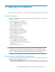
Contents 1 Overview .......................................................................................... 7 Related documentation ................................................................................................................ 8 2 Preparing for installation ..................................................................... 9 Check kit contents .......................................................................................................................
Figures 1 X3410 connections to the MSA ................................................................................ 14 2 X3420 connections to the MSA ................................................................................. 15 3 X3820 connections to the MSA ................................................................................ 16 4 Private connection status .......................................................................................... 18 5 Public connection status .........
Tables 1 Configuration information ........................................................................................ 11 2 Descriptions of RAID levels .......................................................................................
1 Overview A failover cluster is a group of independent computers that work together to increase the availability of applications and services. The clustered servers (called nodes) are connected by physical cables and by software. If one of the cluster nodes fails, another node begins to provide service (a process known as failover). Users experience a minimum of disruptions in service. This document describes the steps required to install and configure a two-node file server failover cluster.
Related documentation The following documents [and websites] provide related information: • • • • • • • • • HP StorageWorks X1000 and X3000 Network Storage System user guide HP StorageWorks 2000sa G2 Modular Smart Array user guide HP StorageWorks 2000fc G2 Modular Smart Array user guide HP Rack Rail Kit installation instructions HP ProLiant Server troubleshooting guide HP Integrated Lights-Out 2 User Guide Network Attached Storage (NAS) from HP StorageWorks: http://www.hp.
2 Preparing for installation Before installing and configuring the cluster, review the following hardware and software requirements. Check kit contents Unpack your High Availability (HA) Shared Storage Solution bundle and confirm that the following components are included.
• • • • Control, and Media Type). Also, compare the settings between the network adapter and the switch it connects to and make sure that no settings are in conflict. If you have private networks that are not routed to the rest of your network infrastructure, ensure that each of these private networks uses a unique subnet. This is necessary even if you give each network adapter a unique IP address.
Gather configuration information Before you begin the process of installing and configuring the hardware, you will need the following configuration information. For easy reference during installation, fill in the Value columns with the appropriate values for your network.
Item Notes iLO 2 management IP address By default, iLO 2 obtains the IP address and subnet mask from DNS/DHCP servers. Default iLO 2 remote management settings Located on the iLO 2 Network Settings tag attached to the storage server Node 1 Value Node 2 Value NOTE: For more detailed information about the Windows Storage Server 2008 failover cluster security model, see Microsoft Knowledge Base article # 947049 at http://support.microsoft.com/kb/947049.
3 Setting up the hardware If your product is already fully racked and cabled, move ahead to “Power on the storage components” on page 17. Install the storage server and MSA components 1. Install the storage server rail kits and storage servers into a server rack by following the HP Rack Rail Kit Installation Instructions. Go to http://www.hp.com/support/manuals, click Disk Storage Systems, and select your storage server to download this document. 2.
Figure 1 X3410 connections to the MSA . Connect the storage servers and MSA to the network After connecting the storage servers to the MSA, make the following power and network connections. 1. Connect the storage server NIC 1 connector to the network. 2. Using the crossover cable, connect the storage server NIC 2 connector to the MSA Controller NIC connector. 3. Connect the power cords to power outlets.
Figure 2 X3420 connections to the MSA . This cabling configuration ensures that all LUNs remain available in the event of a controller failure. Connect the storage servers and MSA to the network After connecting the storage servers to the MSA, make the following power and network connections. 1. Connect the Server 1 NIC 1 connector to the network. 2. Connect the Server 2 NIC 1 connector to the network. 3.
Figure 3 X3820 connections to the MSA . This cabling configuration ensures that all LUNs remain available in the event of a controller failure. Connect the storage servers and MSA to the network After connecting the storage servers to the MSA, make the following power and network connections. 1. Connect the Server 1 NIC 1 connector to the network. 2. Connect the Server 2 NIC 1 connector to the network. 3.
4 Setting up the cluster Power on the storage components IMPORTANT: Because the process of configuring the storage servers includes modifying storage server IP addresses, HP recommends that you initially access the storage servers using either the local KVM or iLO 2 remote management method. If you use the Remote Desktop access method to change the storage server IP addresses, you may be disconnected from the storage server and unable to continue the cluster installation process.
4. Determine which connection is the private connection: a. Right-click one of the connections and select Status. The connection status of the private connection will indicate Local in the IPv4 Connectivity field; the connection status of the public-facing connection will indicate Internet in this field. Figure 4 Private connection status . Figure 5 Public connection status . b. After identifying the private and public connections, click Close to dismiss the connection status dialog boxes.
7. Select Internet Protocol Version 4 (TCP/IPv4) and then click Properties. NOTE: For the purposes of this document, the IPv4 Internet Protocol is the documented IP version. If you are familiar with IPv6 and prefer to use it in your network environment, it is also supported. 8. Select the Use the following IP address radio button and enter the following configuration information: • IP address: 10.24.3.254 • Subnet mask: 255.255.255.0 Figure 6 Setting the private connection static IP address . 9.
12. Repeat the preceding steps on Server 2, setting the private network static IP address with the following configuration information: • IP address: 10.24.3.253 • Subnet mask: 255.255.255.0 For the Server 2 public network IP address, either allow DCHP to automatically configure the IP address or manually configure a static IP address using configuration information assigned by your network administrator. Join both storage servers to the domain 1.
4. Click the Domain radio button and type the name of the domain on which the cluster will reside and then click OK. Figure 8 Computer Name Changes dialog box . 5. When prompted for credentials, enter valid domain account credentials and then click OK. 6. Click OK to accept the domain changes. 7. Click Yes to restart the server. 8. Repeat the preceding steps for Server 2. Log in to the MSA Use the HP StorageWorks MSA Storage Management Utility to log in to the MSA.
4. Log in to MSA Controller A with the default user name manage and password !manage and click Sign In. Configure the storage All clusters must have a shared disk called the witness disk (also referred to as the Quorum disk). The witness disk is a physical disk that is used to make decisions when nodes lose communication with each other. This physical disk is required for all cluster operations.
7. On the Create Volume page, enter a logical name for the witness disk in the Volume name field, enter a volume size of 1 (GB) in the Size field, and check the Map check box. NOTE: HP recommends a volume size of 1 GB for the witness disk because the relatively small size should distinguish it from additional storage volumes to be used for hosting applications and services. 8. Under Select ports from the view or list below, type 1 in the LUN field, and select read-write in the Access list. 9.
Establish the private connection between Server 1 and Server 2 After storage has been configured on the MSA, establish the private connection between Server 1 and Server 2: IMPORTANT: After moving the crossover cable from the MSA to Server 2, you will no longer be able to manage the MSA using the factory-assigned static IP address. To manage the MSA after the private connection between Server 1 and Server 2 has been established, you will need to change the MSA's factory-assigned static IP address of 10.24.
4. Select the MSA and then click Add. Figure 11 Configure MPIO for all storage volumes . 5. When prompted, click Yes to reboot the server. 6. Repeat the preceding steps on Server 2. Initialize and format the storage disks 1. On Server 1, in Server Manager, under Storage, click Disk Management. 2. Right-click the Disk 1 label and select Online to bring the disk online.
3. Right-click the disk, and then click Initialize Disk. Figure 12 Initialize Disk 1 (the witness disk) . 4. In the Initialize Disk dialog box, select the disk to initialize, select a partition style, and then click OK. The disk is initialized as a basic disk. 5. In the storage allocation area, right-click and select New Simple Volume. Figure 13 Create new simple volume . 6. 7.
NOTE: Before moving on to the next task, ensure that all disks have been completely initialized and formatted. After the disks have been completely initialized and formatted, the storage allocation area should indicate the volume name, size, and state (Healthy, for example). Validate the configuration The process of validating your configuration may take a few minutes. If additional storage is configured to be used by the cluster, the validation process takes additional time to complete. 1.
4. On the Select Servers or a Cluster page, enter and add the names of Server 1 and Server 2. Figure 15 Select servers to be validated for the cluster . 5. Select Run all tests and then click Next. 6. Review the details of the Confirmation page and then click Next. Figure 16 Validating the cluster configuration .
7. After the validation tests have run, click View Report to review the validation test results. Use the information provided in the Failover Cluster Validation Report to troubleshoot issues that would prevent the successful creation of the cluster. After addressing the issues, re-run the Validate a Configuration wizard. 8. Click Finish to exit the Validate a Configuration wizard. Create the cluster 1. In the Failover Cluster Management user interface, under Management, click Create a Cluster. 2.
3. On the Before You Begin page, click Next. 4. Select File Server from the list and then click Next. Figure 18 Select Service or Application . 5. Follow the instructions in the wizard to specify the following details: • A name for the clustered file server • The storage volume or volumes that the clustered file server should use NOTE: The clustered file server name is the name of the server that users should use to access their file content. 6.
Verify that the cluster is operational In order to test cluster functionality, move the clustered file server from one server to the other server. When services or applications are moved, they should fail over to the other node in the cluster. • Right-click the clustered file server, select Move this service or application to another node, and click the available choice of node. When prompted, confirm your choice.
Setting up the cluster
A Upgrading a 1–node system to a 2–node system To upgrade the HP StorageWorks X3410 1-Node Network Storage System to a HP StorageWorks X3420 2-Node Network Storage System, you must purchase, install, and configure the following components: • • • • One (1) additional X3400 Network Storage Gateway One (1) HP SC08Ge Host Bus Adapter for the X3400 Network Storage Gateway Three (3) mini-SAS 4x 2M cables One (1) MSA 2000sa G2 Controller (to upgrade the 2000sa G2 Single Controller MSA to a 2000sa G2 Dual Controll
Upgrading a 1–node system to a 2–node system
B Using iLO 2 to access the storage server 1. Locate the iLO 2 Network Settings tag attached to the storage servers and record the default user name, password, and DNS name. 2. From a remote computer, open a standard Web browser and enter the iLO 2 IP address of the storage server. 3. Using the default user information provided on the iLO 2 Network Settings tag, log on to the storage server. 4. On the iLO 2 Status Summary page, click Launch to open the iLO 2 Integrated Remote Console.
Using iLO 2 to access the storage server
C RAID levels supported by the MSA The following table lists the RAID levels supported by the MSA 2012sa and a description of the type of data protection provided. Table 2 Descriptions of RAID levels RAID level Description No RAID Offers no protection against disk failure. If a disk drive fails, data is lost. RAID 0 – Striping (No Fault Tolerance) Offers the greatest capacity and performance without data protection.
RAID level Description RAID 6– Advanced Data Guarding (ADG) Offers the best data protection and is an extension of RAID 5. RAID 6 uses multiple parity sets to store data and can therefore tolerate up to 2 drive failures simultaneously. RAID 6 requires a minimum of 4 drives and is available only if the controller has an enabler. Writer performance is lower than RAID 5 due to parity data updating on multiple drives. It uses two disk for parity; its fault tolerance allows two disks to fail simultaneously.
D Managing the MSA after initial configuration During the initial cluster installation, a factory-assigned static IP address is used to configure storage on the MSA. After moving the crossover cable from the MSA to Server 2 to establish the private heartbeat connection between Server 1 and Server 2, you will no longer be able to manage the MSA using the factory-assigned static IP address. The following procedures can be used to manage the MSA after disconnecting the crossover cable from the MSA. 1.
6. Use the MSA Device Discovery Tool to discover “HP StorageWorks MSA2300sa” storage devices on the local LAN through SNMP. If the MSA Device Discovery tool is not installed on your system, then install the program: a. Insert the MSA2000 Software Support/Documentation CD into the computer’s CD drive. b. When the dialog appears onscreen, double-click AUTORUN.exe. c. From the dialog’s Tools tab, select MSA Device Discovery Tool. d. Complete the installation. 7.