
HP StorageWorks Virtual Array va 7000 family - Installation Guide
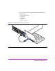
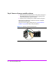

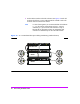
Table Of Contents
- Virtual Array Installation Guide
- Other Information You Will Need
- Operating Environment
- Virtual Array Configurations
- Virtual Array Enclosures
- Hardware Installation
- Configuring the Array Operating Settings
- Step 7. Change the controller default host port behavior
- Step 8. Change the controller port data rate to 2 Gbit/sec
- Step 9. Change the controller port topology
- Step 10. Change the controller loop ID
- Step 11. Change the RAID operating level of the array
- Step 12. Format the array controller enclosure
- Step 13. Power-off the array controller enclosure
- Step 14. Disconnect the RS-232 terminal
- Step 15. Connect fiber optic cables
- Step 16. Power-on all array enclosures
- Installing CommandView SDM Software
- Installing Command View SDM on HP-UX
- Installing Command View SDM on Windows
- Installing Command View SDM on Linux Red Hat
- Final Array Configuration
- Solving Installation Problems

Virtual Array Installation Guide 29
VA 7410
The VA 7410 has two independent back-end Fibre Channel loops to improve
performance. The cabling configuration should balance the distribution of disk
modules across both loops. Here are some things to remember when
connecting the VA 7410 back-end cabling:
— All disks in the controller enclosure are connected to loop 1.
— The first disk enclosure should be connected to loop 2 to balance the
disks.
— Additional disk enclosures should be alternated between loops to
balance the number disks on each loop. The number of disk enclosures
on loop 1 should be equal to or one less than the number of enclosures
on loop 2.
— Do not connect a disk enclosure to both loops.
Refer to Figure 14 when connecting disk enclosures to the VA 7410.
1 Determine which disk enclosures will be on loop 1 and which will be on
loop 2.
2 Connect loop 1 disk enclosures as follows.
a Connect a back-end fiber optic cable from the DISK 1 FC port on array
controller 1 to the PORT 0 or PORT 1 FC connector on the closest disk
enclosure on loop 1.
b Connect a back-end fiber optic cable from the DISK 1 FC port on array
controller 2 to the PORT 0 or PORT 1 FC connector on the same disk
enclosure on loop 1.
c Connect all loop 1 disk enclosures together by connecting fiber optic
cables between the PORT 0 and PORT 1 FC connectors on the
enclosures.
3 Connect loop 2 disk enclosures as follows.
a Connect a back-end fiber optic cable from the DISK 2 FC port on array
controller 1 to the PORT 0 or PORT 1 FC connector on the closest disk
enclosure on loop 2.
b Connect a back-end fiber optic cable from the DISK 2 FC port on array
controller 2 to the PORT 0 or PORT 1 FC connector on the same disk
enclosure on loop 2.
c Connect all loop 2 disk enclosures together by connecting fiber optic
cables between the PORT 0 and PORT 1 FC connectors on the
enclosures.