
HP StorageWorks Virtual Array va 7000 family - Installation Guide
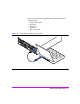
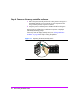

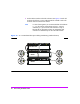
Table Of Contents
- Virtual Array Installation Guide
- Other Information You Will Need
- Operating Environment
- Virtual Array Configurations
- Virtual Array Enclosures
- Hardware Installation
- Configuring the Array Operating Settings
- Step 7. Change the controller default host port behavior
- Step 8. Change the controller port data rate to 2 Gbit/sec
- Step 9. Change the controller port topology
- Step 10. Change the controller loop ID
- Step 11. Change the RAID operating level of the array
- Step 12. Format the array controller enclosure
- Step 13. Power-off the array controller enclosure
- Step 14. Disconnect the RS-232 terminal
- Step 15. Connect fiber optic cables
- Step 16. Power-on all array enclosures
- Installing CommandView SDM Software
- Installing Command View SDM on HP-UX
- Installing Command View SDM on Windows
- Installing Command View SDM on Linux Red Hat
- Final Array Configuration
- Solving Installation Problems

28 Virtual Array Installation Guide
Front-end fiber optic connections depend on the type of connectors used by the
controller and the type of host adapter or type of connector in the hub or
switch.
— The VA 7100 controller uses GBICs with SC (large form factor)
connectors. It only supports host adapters with SC connectors, and uses
cables with SC-SC connectors.
— The VA 7110/7400/7410 controller uses integrated LC (small form
factor) connectors. It supports host adapters with LC connectors, using
LC-LC cables, or host adapters with SC connectors, using LC-SC adapter
cables with couplers.
See Figure 15 for information on supported fiber optic cables and
configurations.
Connecting back-end fiber optic cables and setting address
switches (VA 7110/7400/7410 Only)
The VA 7400/7410 supports up to 6 external disk enclosures and the
VA 7110 supports up to 2 disk enclosures. It is recommended that the back-
end connections be made using the shortest possible FC cables.
VA 7400 and VA 7110
Refer to Figure 12 when connecting disk enclosures to a VA 7110, and Figure
13 when connecting disk enclosures to a VA 7400. Up to 2 disk enclosures
can be connected to an VA 7110, and up to 6 disk enclosures can be
connected to a VA 7400.
1 Connect a back-end fiber optic cable from the DISK FC connector on array
controller 1 to the PORT 0 or PORT 1 FC-AL connector on the closest disk
enclosure.
2 Connect a back-end fiber optic cable from the DISK FC connector on array
controller 2 to the PORT 0 or PORT 1 FC-AL connector on the same disk
enclosure.
3 Connect all disk enclosures together by connecting fiber optic cables
between the PORT 0 and PORT 1 FC-AL connectors on the enclosures.
4 Set the address switches on the disk enclosures. See Figure 13. Each disk
enclosure must have a unique address. Both link controller cards in the
enclosure must be set to the same address.
Note It is recommended that you set the disk enclosure addresses
starting with 0 and incrementing by 1 for each enclosure.