
HP StorageWorks Virtual Array 7000 Family User and Service Guide (January 2005)
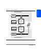
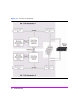
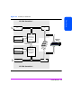
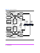
Table Of Contents
- Warranty Information
- Product Overview
- System Configurations
- Lowest Entry Point, Non-HA Minimum Configuration (VA 7100 only)
- Lowest Entry Point, Non-HA Minimum Configuration (VA 7410)
- Entry Level Non-Cluster With Path Redundancy (All VA arrays)
- Entry Level Cluster with Path Redundancy High Availability (VA 7410)
- Midrange Non-Cluster (All VA arrays)
- Midrange Non-Cluster (VA 7410)
- Midrange Non-Cluster with Full Storage Path Redundancy (All VA Arrays)
- Typical Non-Clustered with Path Redundancy (VA 7410)
- Typical Clustered Configuration (All VA models)
- Typical Clustered Configuration (VA 7410)
- HP-UX MC Service Guard or Windows 2000 Cluster (All VA arrays)
- Highly Redundant Cluster (VA 7410)
- Typical Highly Redundant Cluster (All VA models)
- Typical Highly Redundant Cluster (VA 7410)
- Troubleshooting
- Servicing & Upgrading
- Specifications & Regulatory Statements

52 Product Overview
Data I/O Architecture
The internal architecture of the array controllers is designed to optimize the
speed of data transfer between the array and the host. The internal
architecture for each product is illustrated in Figures 20, 22, and 23.
The following major components are involved in the flow of data through the
array:
■ Data flow processor - manages movement of data over the internal high-
speed busses. The processor also manages the flow of data into and out of
the ECC cache.
■ ECC cache - provides temporary storage of data for high-speed access.
■ High-speed busses - provide the data path from the host to the disk media.
The N-Way bus provides the communication link between controllers for
management and redundancy.
■ FC ports - provide the interface to the host and the back-end disk
enclosures. The VA 7410 includes additional FC ports for added flexibility
and performance.