
HP StorageWorks Virtual Array 7000 Family User and Service Guide (January 2005)
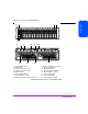
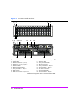
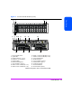

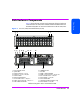
Table Of Contents
- Warranty Information
- Product Overview
- System Configurations
- Lowest Entry Point, Non-HA Minimum Configuration (VA 7100 only)
- Lowest Entry Point, Non-HA Minimum Configuration (VA 7410)
- Entry Level Non-Cluster With Path Redundancy (All VA arrays)
- Entry Level Cluster with Path Redundancy High Availability (VA 7410)
- Midrange Non-Cluster (All VA arrays)
- Midrange Non-Cluster (VA 7410)
- Midrange Non-Cluster with Full Storage Path Redundancy (All VA Arrays)
- Typical Non-Clustered with Path Redundancy (VA 7410)
- Typical Clustered Configuration (All VA models)
- Typical Clustered Configuration (VA 7410)
- HP-UX MC Service Guard or Windows 2000 Cluster (All VA arrays)
- Highly Redundant Cluster (VA 7410)
- Typical Highly Redundant Cluster (All VA models)
- Typical Highly Redundant Cluster (VA 7410)
- Troubleshooting
- Servicing & Upgrading
- Specifications & Regulatory Statements

Product Overview 27
Product Overview
A new disk can be added at any time, even while the array is operating.
When a disk is replaced, the array applies power to the disk in a controlled
manner to eliminate power stresses. The array controller will recognize that a
new disk has been added and, if the Auto Include feature is enabled, will
include the disk in the array configuration automatically. However, to make the
additional capacity available to the host, a new logical drive must be created
and configured into the operating system.
A label on the disk drive provides the following information:
— Capacity in gigabytes: 18G, 36G, 73G, or 146G
— Interface: FC (Fibre Channel)
— Rotational speed in revolutions per minute: 10K or 15K
Note A red zero (0) on the capacity label distinguishes a disk drive
filler panel from a disk drive.
Image Disks
When the array is formatted, the array controller selects two disks as image
disks. On the VA 7410 a third disk is identified as a backup in the event one of
the primary image disks fails. Because it is not possible to predict which disks
will be selected as the image disks, the management software must be used to
determine which disks have been selected.
The image disks serve two functions:
■ The image disks have space reserved for copies, or “images”, of the write
cache and virtualization data structures stored in the controller NVRAM.
During a shutdown, a complete copy of the NVRAM is stored on both
image disks. If the maps are lost, they can be restored from the image
disks.
■ When resiliency map settings are set to the factory default (Normal
Resiliency), changes to the maps, which have occurred since the last
shutdown, are updated every 4 seconds on the image disks.
Note A shutdown makes the disk set independent of its controller.
Because all of the necessary mapping information is on the
image disks, it is possible to install a new controller or move the
entire disk set to another controller. The new controller will
determine that it has a new disk set, and will logically attach
itself to those disks.