
HP StorageWorks Virtual Array 7000 Family User and Service Guide (January 2005)
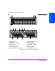
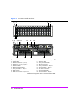
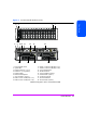

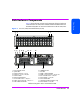
Table Of Contents
- Warranty Information
- Product Overview
- System Configurations
- Lowest Entry Point, Non-HA Minimum Configuration (VA 7100 only)
- Lowest Entry Point, Non-HA Minimum Configuration (VA 7410)
- Entry Level Non-Cluster With Path Redundancy (All VA arrays)
- Entry Level Cluster with Path Redundancy High Availability (VA 7410)
- Midrange Non-Cluster (All VA arrays)
- Midrange Non-Cluster (VA 7410)
- Midrange Non-Cluster with Full Storage Path Redundancy (All VA Arrays)
- Typical Non-Clustered with Path Redundancy (VA 7410)
- Typical Clustered Configuration (All VA models)
- Typical Clustered Configuration (VA 7410)
- HP-UX MC Service Guard or Windows 2000 Cluster (All VA arrays)
- Highly Redundant Cluster (VA 7410)
- Typical Highly Redundant Cluster (All VA models)
- Typical Highly Redundant Cluster (VA 7410)
- Troubleshooting
- Servicing & Upgrading
- Specifications & Regulatory Statements

Product Overview 25
Product Overview
DIMMs
Each array controller includes one or two ECC SDRAM DIMMs that are battery
backed up and mirrored with the dual controller. This memory is used for the
read and write cache, and for the virtualization data structures. These data
structures provide the logical-to-physical mapping required for virtualization
and are vital to the operation of the array. Without these data structures, all
data in the array is inaccessible.
Note The DIMMs are a critical component in maintaining correct
operation of the array. Use extreme caution when replacing or
modifying the DIMM configuration.
Table 25 on page 136 shows the valid configuration of DIMMs for each
controller cache size. In a dual controller configuration, both controllers must
have the same cache size.
Battery
Note The array controller battery is a critical component in
maintaining the virtualization data structures during a power
loss when the array has not successfully completed a shutdown.
Exhausting the battery power in this state may result in data loss.
Each array controller includes a Lithium Ion-type battery with a built-in
microprocessor. The battery provides backup power to the DIMMs in the event
of a power failure or if array power is switched off. The batteries provide
power for minimum of 84 hours. If line power is lost, the green BATTERY LED
will flash with a 5% duty cycle while powering the DIMMs. A fully charged
battery will maintain DIMM memory contents for a minimum of three days.
(The three-day specification includes derating for battery life, temperature, and
voltage.) If the battery loses its charge, or if it is removed from the controller,
the DIMMs will not be powered and memory maps will be lost.
Battery Status. The controller constantly interrogates the battery for its status. If
the battery cannot maintain memory contents for a minimum of three days, a
warning will notify the operator to replace the battery. Every six months, the
battery performs a self-test to determine its charge status. Then it is fully
discharged and fully recharged to optimize battery life. This action is not
indicated by software or LEDs. In a dual controller configuration, only one
battery at a time is discharged and recharged. If the battery becomes
discharged during normal operation, the green BATTERY LED will turn off and
the amber BATTERY LED will turn on. If the battery has low charge during a