
HP StorageWorks Virtual Array 7000 Family User and Service Guide (January 2005)

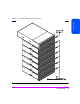
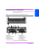
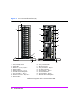
Table Of Contents
- Warranty Information
- Product Overview
- System Configurations
- Lowest Entry Point, Non-HA Minimum Configuration (VA 7100 only)
- Lowest Entry Point, Non-HA Minimum Configuration (VA 7410)
- Entry Level Non-Cluster With Path Redundancy (All VA arrays)
- Entry Level Cluster with Path Redundancy High Availability (VA 7410)
- Midrange Non-Cluster (All VA arrays)
- Midrange Non-Cluster (VA 7410)
- Midrange Non-Cluster with Full Storage Path Redundancy (All VA Arrays)
- Typical Non-Clustered with Path Redundancy (VA 7410)
- Typical Clustered Configuration (All VA models)
- Typical Clustered Configuration (VA 7410)
- HP-UX MC Service Guard or Windows 2000 Cluster (All VA arrays)
- Highly Redundant Cluster (VA 7410)
- Typical Highly Redundant Cluster (All VA models)
- Typical Highly Redundant Cluster (VA 7410)
- Troubleshooting
- Servicing & Upgrading
- Specifications & Regulatory Statements
Product Overview 19
Product Overview
Controller Enclosure Components
Figure 2 through Figure 6 show the front and rear panel components of the VA
7000 Family controller enclosures.
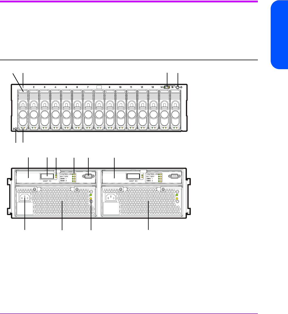
Figure 2 VA 7100 Factory-Racked & Field-Racked Controller Enclosure (A/AZ)
*Reference designator used in CommandView SDM
1 - Power/Standby Switch 9 - HOST FC LEDs
2 - System LEDs 10 - Array Controller LEDs
3 - Disk Drive Slot No. 1 (of 15) 11 - RS-232 Connector
4 - Disk Drive 1 (of 15) - M/D1* 12 - Array Controller 2 - M/C2*
5 - Disk Drive LEDs 13 - Power Module 1 - M/P1*
6 - ESD Ground Receptacle 14 - AC Power Connector
7 - Array Controller 1- M/C1* 15 - Power Module LEDs
8 - HOST FC Connector - M/C1.H1* 16 - Power Module 2 - M/P2*
21
3
4
7
89
10 11
12
16
56
14 13 15