
HP StorageWorks Virtual Array 7000 Family User and Service Guide (January 2005)

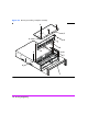

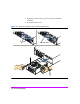
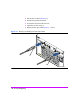
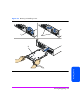
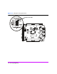
Table Of Contents
- Warranty Information
- Product Overview
- System Configurations
- Lowest Entry Point, Non-HA Minimum Configuration (VA 7100 only)
- Lowest Entry Point, Non-HA Minimum Configuration (VA 7410)
- Entry Level Non-Cluster With Path Redundancy (All VA arrays)
- Entry Level Cluster with Path Redundancy High Availability (VA 7410)
- Midrange Non-Cluster (All VA arrays)
- Midrange Non-Cluster (VA 7410)
- Midrange Non-Cluster with Full Storage Path Redundancy (All VA Arrays)
- Typical Non-Clustered with Path Redundancy (VA 7410)
- Typical Clustered Configuration (All VA models)
- Typical Clustered Configuration (VA 7410)
- HP-UX MC Service Guard or Windows 2000 Cluster (All VA arrays)
- Highly Redundant Cluster (VA 7410)
- Typical Highly Redundant Cluster (All VA models)
- Typical Highly Redundant Cluster (VA 7410)
- Troubleshooting
- Servicing & Upgrading
- Specifications & Regulatory Statements

Servicing & Upgrading 127
Servicing & Upgrading
Link Controller Cards (LCCs)
Caution The LCC can be damaged by electrostatic discharge. Use the
ESD kit provided when removing and installing an LCC.
The DS 2400 Disk System and the DS 2405 Disk System use
different LCCs. Do not mix LCCs in the same disk enclosure.
To prevent data loss, it is recommended that a full backup be
performed before removing an LCC.
Do not operate the disk enclosure for more than 5 minutes with
an LCC removed. An LCC must be installed in the slot to maintain
proper airflow in the enclosure. If necessary, use the foam in the
replacement LCC packaging to temporarily fill the slot.
Removing an LCC
(HP Service Personnel Only)
1 Remove the fiber optic cables (Figure 51, 1 and 2).
Note Depending on your configuration, Port 0 or Port 1 FC connectors
may or may not have a fiber optic cable connected to it.
Loopback cables are neither required nor recommended on
unused FC connectors.
2 Loosen the cam lever screw (Figure 52, 1) with a T-10 driver or flat-blade
screwdriver.
3 Pull out both cam levers (2) at the same time.
4 Pull the LCC (3) out of the slot.
Installing an LCC
(HP Service Personnel Only)
1 If the LCC is being installed in a DS 2405 Disk System attached to a
VA 7400, set the FC Loop Speed switch on the LCC to the 1GB/s position.
See Figure 53.
Note The FC Loop Speed switch does not have to be changed when
installing an LCC in a DS 2405 attached to a VA 7410 or
VA 7110. The default 2GB/s setting is used on these products.