
HP StorageWorks Virtual Array 7000 Family User and Service Guide (January 2005)

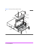

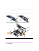
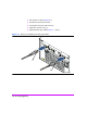
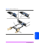
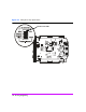
Table Of Contents
- Warranty Information
- Product Overview
- System Configurations
- Lowest Entry Point, Non-HA Minimum Configuration (VA 7100 only)
- Lowest Entry Point, Non-HA Minimum Configuration (VA 7410)
- Entry Level Non-Cluster With Path Redundancy (All VA arrays)
- Entry Level Cluster with Path Redundancy High Availability (VA 7410)
- Midrange Non-Cluster (All VA arrays)
- Midrange Non-Cluster (VA 7410)
- Midrange Non-Cluster with Full Storage Path Redundancy (All VA Arrays)
- Typical Non-Clustered with Path Redundancy (VA 7410)
- Typical Clustered Configuration (All VA models)
- Typical Clustered Configuration (VA 7410)
- HP-UX MC Service Guard or Windows 2000 Cluster (All VA arrays)
- Highly Redundant Cluster (VA 7410)
- Typical Highly Redundant Cluster (All VA models)
- Typical Highly Redundant Cluster (VA 7410)
- Troubleshooting
- Servicing & Upgrading
- Specifications & Regulatory Statements

Servicing & Upgrading 125
Servicing & Upgrading
Disk Enclosure Removal & Installation Procedures
Disk Drives
See "Disk Drives" on page 98 for information on removing and installing disk
drives.
Disk Drive Filler Panels
See "Disk Drive Filler Panels" on page 100 for information on removing and
installing disk drive filler panels.
Power Modules
Removing a Power Module
Caution Do not operate the array for more than 2 minutes with a power
module removed, or the array may automatically initiate a
shutdown. At least one power module must be installed and
operational at all times to maintain adequate power and airflow.
Always disconnect the power cord from the power module
before removing it from the enclosure. Failure to disconnect
power may result in power spikes that could damage the disk
drives.
1 Disconnect the power cord.
2 Loosen the cam lever screws (Figure 50, 1) with a T-10 driver or flat-blade
screwdriver.
3 Pull out both cam levers (2) at the same time.
4 Pull the power module (3) out of the slot.
Installing a Power Module
1 Pull out both cam levers (Figure 50, 2) at the same time.
2 Push the power module (3) firmly into the slot.
3 Push in both cam levers at the same time.