
HP StorageWorks Virtual Array 7000 Family User and Service Guide (January 2005)

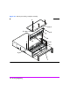

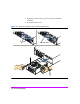
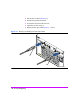
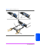
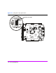
Table Of Contents
- Warranty Information
- Product Overview
- System Configurations
- Lowest Entry Point, Non-HA Minimum Configuration (VA 7100 only)
- Lowest Entry Point, Non-HA Minimum Configuration (VA 7410)
- Entry Level Non-Cluster With Path Redundancy (All VA arrays)
- Entry Level Cluster with Path Redundancy High Availability (VA 7410)
- Midrange Non-Cluster (All VA arrays)
- Midrange Non-Cluster (VA 7410)
- Midrange Non-Cluster with Full Storage Path Redundancy (All VA Arrays)
- Typical Non-Clustered with Path Redundancy (VA 7410)
- Typical Clustered Configuration (All VA models)
- Typical Clustered Configuration (VA 7410)
- HP-UX MC Service Guard or Windows 2000 Cluster (All VA arrays)
- Highly Redundant Cluster (VA 7410)
- Typical Highly Redundant Cluster (All VA models)
- Typical Highly Redundant Cluster (VA 7410)
- Troubleshooting
- Servicing & Upgrading
- Specifications & Regulatory Statements

122 Servicing & Upgrading
Midplane Assembly
Caution
— To prevent data loss, it is recommended that a full backup be performed
before removing a midplane assembly.
— The midplane assembly can be damaged by electrostatic discharge.
Use the ESD kit provided when removing and installing the midplane
assembly.
— The midplane assembly is tied directly to the enclosure. Once a
midplane assembly has been installed in an enclosure, you cannot re-
use it in another enclosure. The serial number and worldwide name
(WWN) of the enclosure are stored in redundant EEPROMs on the
midplane assembly.
Removing a Midplane Assembly
(HP Service Personnel Only)
1 Perform an array shutdown.
2 Remove all of the disk drives. See "Removing a Disk Drive" on page 98.
Note The controllers and power modules do not need to be completely
removed from the array chassis - only disengaged.
3 Disengage the array controller cards 1 inch (2.5 cm) from the midplane.
See "Removing an Array Controller" on page 107.
4 Disengage the power modules 1 inch (2.5 cm) from the midplane. See
"Removing a Power Module" on page 102.
5 Racked arrays only: Remove the chassis mounting screws from the rack
and pull the array chassis 2 inches (5 cm) out of the rack.
Note Verify that pulling the array chassis out of the rack will not stress
or damage the cables connected to the rear of the chassis.
Deskside arrays only: Remove the chassis from the deskside assembly (see
HP StorageWorks VA 7100 Deskside Assembly Conversion Kit
Instructions)
.
6 Remove the front bezel (Figure 49, 1).
7 Remove three T-10 screws (2) from the chassis top cover (6).