
HP StorageWorks Virtual Array 7000 Family User and Service Guide (January 2005)
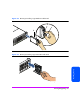
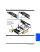
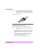
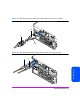
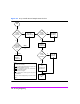
Table Of Contents
- Warranty Information
- Product Overview
- System Configurations
- Lowest Entry Point, Non-HA Minimum Configuration (VA 7100 only)
- Lowest Entry Point, Non-HA Minimum Configuration (VA 7410)
- Entry Level Non-Cluster With Path Redundancy (All VA arrays)
- Entry Level Cluster with Path Redundancy High Availability (VA 7410)
- Midrange Non-Cluster (All VA arrays)
- Midrange Non-Cluster (VA 7410)
- Midrange Non-Cluster with Full Storage Path Redundancy (All VA Arrays)
- Typical Non-Clustered with Path Redundancy (VA 7410)
- Typical Clustered Configuration (All VA models)
- Typical Clustered Configuration (VA 7410)
- HP-UX MC Service Guard or Windows 2000 Cluster (All VA arrays)
- Highly Redundant Cluster (VA 7410)
- Typical Highly Redundant Cluster (All VA models)
- Typical Highly Redundant Cluster (VA 7410)
- Troubleshooting
- Servicing & Upgrading
- Specifications & Regulatory Statements

Servicing & Upgrading 109
Servicing & Upgrading
Caution The array controller can be damaged by electrostatic discharge.
Use the ESD kit provided when removing and installing an array
controller.
To prevent data loss, it is recommended that a full backup be
performed before removing an array controller.
Do not operate the array for more than 5 minutes with an array
controller or filler panel removed. Either an array controller or
filler panel must be installed to maintain proper airflow in the
controller enclosure. Use the foam in the replacement array
controller packaging to temporarily plug the empty slot.
1 Perform any necessary prepatory steps indicated in Figure 42.
2 VA 7100: Remove the fiber optic cable from the GBIC (see Figure 39).
VA 7110/7400/7410: Remove the fiber optic cables from the DISK FC
and HOST FC connectors (see Figure 40).
3 VA 7100 only: Remove the GBIC (see Figure 39, 3).
4 VA 7100: Slide the latch (Figure 43, 1) all the way to the left.
VA 7110/7400/7410: Loosen the cam lever screw (Figure 44, 1) with a T-
10 driver or flat-blade screwdriver.
5 VA 7100: Press down the lock (Figure 43, 2) and pull out the cam lever (3).
VA 7110/7400/7410: Pull out the cam lever (Figure 44, 2).
WARNING A hot surface is located on the underside of the array controller
by the middle of the right-hand edge (facing the rear panel). To
avoid burn injury, only touch the edges of the array controller.
Do not touch the underside.
Caution When the cam lever is pulled out, an early warning switch is
activated which suspends mirroring between dual controllers
and terminates all I/Os to the controllers.
6 Grasp the cam lever and slide the array controller out 4 inches (10 cm)
(Figure 43 or Figure 44).
7 Grasp the edges of the array controller with both hands and pull it out of
the slot.
8 If the array controller was removed for a DIMM failure :
Go to "Installing an Array Controller" on page 110.