
HP StorageWorks Virtual Array 7000 Family User and Service Guide (January 2005)
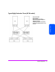
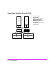
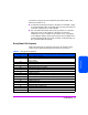
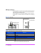
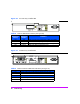
Table Of Contents
- Warranty Information
- Product Overview
- System Configurations
- Lowest Entry Point, Non-HA Minimum Configuration (VA 7100 only)
- Lowest Entry Point, Non-HA Minimum Configuration (VA 7410)
- Entry Level Non-Cluster With Path Redundancy (All VA arrays)
- Entry Level Cluster with Path Redundancy High Availability (VA 7410)
- Midrange Non-Cluster (All VA arrays)
- Midrange Non-Cluster (VA 7410)
- Midrange Non-Cluster with Full Storage Path Redundancy (All VA Arrays)
- Typical Non-Clustered with Path Redundancy (VA 7410)
- Typical Clustered Configuration (All VA models)
- Typical Clustered Configuration (VA 7410)
- HP-UX MC Service Guard or Windows 2000 Cluster (All VA arrays)
- Highly Redundant Cluster (VA 7410)
- Typical Highly Redundant Cluster (All VA models)
- Typical Highly Redundant Cluster (VA 7410)
- Troubleshooting
- Servicing & Upgrading
- Specifications & Regulatory Statements

Troubleshooting 77
Troubleshooting
A Link Down warning state can be reported by the CVGUI if either of the
following two failures occur:
■ If a host Fibre Channel loop fails due to the failure of a host HBA, a faulty
or disconnected fiber cable, a faulty GBIC (VA 7100 only), or the failure of
a data flow component on an array controller.
■ If an array Fibre Channel loop fails due to a port failure on a disk drive,
faulty loop circuitry on the midplane, or the failure of a data flow
component on an array controller. If a port failure occurs, a port bypass
circuit will bypass that part of the loop and the first array controller will re-
route the data through the second array controller, via the internal N-way
bus, to the other Fibre Channel loop.
Array Power-On Sequence
Table 5 shows the power-on sequence for the array. This sequence can be
viewed via the Virtual Front Panel (VFP) when the array is powered on.
Table 5 Array Power-On Sequence
Step No. (Hex) Description of Array Operation
02 Power-on self-test complete.
04 Check array serial number. Configure NVRAM for maps. Initialize all NVRAM on
both controllers.
06 Initialize internals.
08 Initialize array scheduler.
0A Search for backend devices.
0C Backend device discovery complete.
0E Enable power supply manager to shutdown if needed.
12 Initialize maps and cache via upload from image disks. Attach array to volume set.
16 Enable hot plugging.
18 Enable warning services.
1A Reserved.
1C Setup internal data structures based on backend discovery.
1D Enable frontend ports.
1E Initialize array clocks.
20 Setup internal data structures.
22 Synchronize both controller clocks.
24 Startup complete. Enable scheduler. Allow writes to disks.
26 Initialization complete.