
HP StorageWorks Virtual Array 7000 Family User and Service Guide (January 2005)
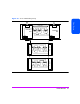
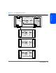
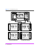
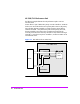
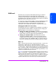
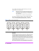
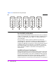
Table Of Contents
- Warranty Information
- Product Overview
- System Configurations
- Lowest Entry Point, Non-HA Minimum Configuration (VA 7100 only)
- Lowest Entry Point, Non-HA Minimum Configuration (VA 7410)
- Entry Level Non-Cluster With Path Redundancy (All VA arrays)
- Entry Level Cluster with Path Redundancy High Availability (VA 7410)
- Midrange Non-Cluster (All VA arrays)
- Midrange Non-Cluster (VA 7410)
- Midrange Non-Cluster with Full Storage Path Redundancy (All VA Arrays)
- Typical Non-Clustered with Path Redundancy (VA 7410)
- Typical Clustered Configuration (All VA models)
- Typical Clustered Configuration (VA 7410)
- HP-UX MC Service Guard or Windows 2000 Cluster (All VA arrays)
- Highly Redundant Cluster (VA 7410)
- Typical Highly Redundant Cluster (All VA models)
- Typical Highly Redundant Cluster (VA 7410)
- Troubleshooting
- Servicing & Upgrading
- Specifications & Regulatory Statements

42 Product Overview
VA 7400/7410 Redundancy Groups
The VA 7400 and VA 7410 have two redundancy groups (RG1 and RG2). See
Figure 15 and Figure 16.
■ Controller 1 manages Redundancy Group 1 (RG1), which consists of all
disks in odd numbered slots (D1, D3, D5, D7, D9, D11, D13, D15) in the
controller enclosure, and in all disk enclosures (JA0-JA5).
■ Controller 2 manages Redundancy Group 2 (RG2), which consists of all
disks in even numbered slots (D2, D4, D6, D8, D10, D12, D14) in the
controller enclosure, and in all disk enclosures (JA0-JA5).
On the VA 7410, Redundancy Group are independent of both back-end FC
loops. Management of the redundancy group disks is independent of which
disk enclosure LCC the array controller is connected to. For example, array
controller 1 can be connected to LCC 1 or LCC 2 and it will still manage the
disks in the odd numbered slots.
The array controllers are connected via an internal N-Way bus, which used for
controller-to-controller communication and loop failover.