
HP StorageWorks Virtual Array 7000 Family User and Service Guide (January 2005)
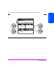
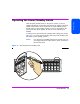
Table Of Contents
- Warranty Information
- Product Overview
- System Configurations
- Lowest Entry Point, Non-HA Minimum Configuration (VA 7100 only)
- Lowest Entry Point, Non-HA Minimum Configuration (VA 7410)
- Entry Level Non-Cluster With Path Redundancy (All VA arrays)
- Entry Level Cluster with Path Redundancy High Availability (VA 7410)
- Midrange Non-Cluster (All VA arrays)
- Midrange Non-Cluster (VA 7410)
- Midrange Non-Cluster with Full Storage Path Redundancy (All VA Arrays)
- Typical Non-Clustered with Path Redundancy (VA 7410)
- Typical Clustered Configuration (All VA models)
- Typical Clustered Configuration (VA 7410)
- HP-UX MC Service Guard or Windows 2000 Cluster (All VA arrays)
- Highly Redundant Cluster (VA 7410)
- Typical Highly Redundant Cluster (All VA models)
- Typical Highly Redundant Cluster (VA 7410)
- Troubleshooting
- Servicing & Upgrading
- Specifications & Regulatory Statements
Product Overview 35
Product Overview
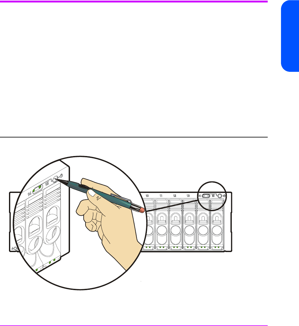
Operating the Power/Standby Switch
When the power/standby switch is in the “power” position, ac power is
applied to the primary and secondary sides of the power supplies in the power
module and all of the dc circuits in the array are active. When the power/
standby switch is in the “standby” position, ac power is only applied to the
primary side of the power supplies; all of the dc circuits in the array are
disabled.
To switch power on, push in the power/standby switch to the “power” position.
See Figure 11.To switch power to standby, push in the power/standby switch
then release it to the “standby” position.
Caution If it is necessary to completely remove power from the array, you
must unplug both power cords from the ac power connectors on
the array rear panel.
Figure 11 Operating the Power/Standby Switch