
HP StorageWorks Virtual Array 7000 Family User and Service Guide (January 2005)
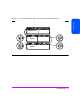
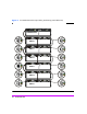
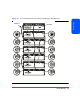
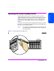
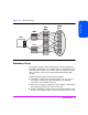
Table Of Contents
- Warranty Information
- Product Overview
- System Configurations
- Lowest Entry Point, Non-HA Minimum Configuration (VA 7100 only)
- Lowest Entry Point, Non-HA Minimum Configuration (VA 7410)
- Entry Level Non-Cluster With Path Redundancy (All VA arrays)
- Entry Level Cluster with Path Redundancy High Availability (VA 7410)
- Midrange Non-Cluster (All VA arrays)
- Midrange Non-Cluster (VA 7410)
- Midrange Non-Cluster with Full Storage Path Redundancy (All VA Arrays)
- Typical Non-Clustered with Path Redundancy (VA 7410)
- Typical Clustered Configuration (All VA models)
- Typical Clustered Configuration (VA 7410)
- HP-UX MC Service Guard or Windows 2000 Cluster (All VA arrays)
- Highly Redundant Cluster (VA 7410)
- Typical Highly Redundant Cluster (All VA models)
- Typical Highly Redundant Cluster (VA 7410)
- Troubleshooting
- Servicing & Upgrading
- Specifications & Regulatory Statements

34 Product Overview
Power Modules
The disk enclosure is shipped with two fully redundant power modules. Each
power module contains:
■ An autoranging power supply that converts ac input power to dc output
power for use by the other array components. The power supplies share the
power load under non-fault conditions. If one power supply fails, the other
supply delivers the entire load to maintain power for the array. Each power
supply uses a separate power cord. Both power supplies can be plugged
into a common power source, or each supply can be plugged into a
separate circuit to provide power source redundancy.
■ One internal blower, which provides airflow and maintains the proper
operating temperature within the array enclosure. If the blower fails, a fault
will occur. The other power module will continue to operate and its blower
will continue to cool the enclosure. Even if a power supply fails, the blower
within the power module will continue to operate; dc power for the blower
is distributed from the midplane.