
HP StorageWorks Virtual Array 7000 Family User and Service Guide (January 2005)
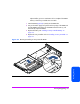

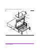
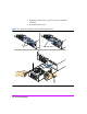
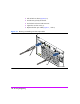
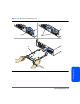
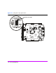
Table Of Contents
- Warranty Information
- Product Overview
- System Configurations
- Lowest Entry Point, Non-HA Minimum Configuration (VA 7100 only)
- Lowest Entry Point, Non-HA Minimum Configuration (VA 7410)
- Entry Level Non-Cluster With Path Redundancy (All VA arrays)
- Entry Level Cluster with Path Redundancy High Availability (VA 7410)
- Midrange Non-Cluster (All VA arrays)
- Midrange Non-Cluster (VA 7410)
- Midrange Non-Cluster with Full Storage Path Redundancy (All VA Arrays)
- Typical Non-Clustered with Path Redundancy (VA 7410)
- Typical Clustered Configuration (All VA models)
- Typical Clustered Configuration (VA 7410)
- HP-UX MC Service Guard or Windows 2000 Cluster (All VA arrays)
- Highly Redundant Cluster (VA 7410)
- Typical Highly Redundant Cluster (All VA models)
- Typical Highly Redundant Cluster (VA 7410)
- Troubleshooting
- Servicing & Upgrading
- Specifications & Regulatory Statements

Servicing & Upgrading 123
Servicing & Upgrading
8 Using a flat-blade screwdriver, push up the two front top-cover side-clips
(3) and pop the top cover up slightly.
9 Twist the screwdriver blade in the rear gaps (4) on the side of the chassis,
directly behind the top cover.
10 Place a screwdriver blade in a vertical position in the slots (5) on top of the
chassis directly behind the top cover. Hit the handle of the screwdriver with
the palm of your hand until the top cover moves forward 3/16 inch (0.5
cm).
11 Slide the top cover (6) off the chassis.
12 Lift the lightpipe (7) out of the chassis slots and remove it from the chassis.
13 Press the power/standby switch shaft (8) all the way in and remove it from
the chassis.
14 With the T-15 driver provided in the midplane assembly kit, remove 9
screws (9) from the midplane assembly.
15 Remove the midplane assembly (10) from the chassis.
Installing a Midplane Assembly
(HP Service Personnel Only)
Note Installing a midplane assembly is the reverse of removing a
midplane assembly.