
HP StorageWorks Scalable File Share System Installation and Upgrade Guide Version 2.2

Preparing for the installation2–16
2.4.2.2.2 Asymmetric dual Gigabit Ethernet configuration
All configurations where there are more interfaces on the HP SFS servers than there are on the client nodes
are asymmetric configurations. Asymmetric configurations are more complicated than symmetric
configurations because it is not possible to logically split the networks and still retain full connectivity
between all systems. This may not be an issue if the client nodes have only a single link and do not need to
communicate with each other, but the HP SFS servers must be able to communicate with each other at all
times.
Dual-link server to single-link client nodes configuration
Figure 2-9 shows a configuration where the clients can communicate with each other and both links on each
HP SFS server are utilized.
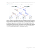
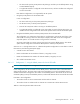
Figure 2-9 Dual-link server to single-link client nodes — networks physically separate
To use both of the server interfaces, the client IP addresses are split equally between the two logically
separate networks of the HP SFS servers. This configuration provides the full bandwidth from the HP SFS
server only when a suitable number of client nodes in each IP address range are active, because each server
only allows a connection from an interface if it can send a message to that interface. This restriction is
necessary to ensure that the routing tables are correct and that both server interfaces are used. Client
intercommunication is achieved by a less restrictive netmask that allows the client nodes on the 10.128.0.0
network to reach the client nodes on the 10.128.8.0 network clients and vice versa. This less restrictive
netmask must not be used on any HP SFS server interface; if it was used, it would prohibit the correct use
of both interfaces and would be in contradiction of the requirement that server interfaces must be configured
on separate logical networks.
The physical links are also important in this case, to ensure that the requirement for interfaces on the same
logical network to be connected via the fastest possible pathway through any intermediary hardware is met.
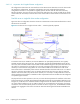
In Figure 2-9, all HP SFS server interfaces that are configured on the 10.128.0.0 network are connected to
one switch and all interfaces on the 10.128.8.0 network are connected to the second switch. If all server
connections were connected serially to the two switches as shown in Figure 2-10, the bandwidth would be
reduced to the aggregate of the switch connections rather than allowing the full HP SFS bandwidth to be
utilized.