
HP StorageWorks Scalable File Share System Installation and Upgrade Guide Version 2.2

Hardware overview 1–23
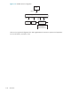
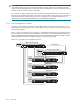
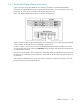
1.6.5 The Gigabit Ethernet interconnect
Figure 1-17 shows how ProLiant DL360 servers are connected to a Gigabit Ethernet interconnect. The
Gigabit Ethernet switch is not part of the HP SFS system—you may choose your own switch technology. The
switch shown in Figure 1-17 is for illustrative purposes only.
Figure 1-17 shows a system using ProLiant DL360 servers; the connections in a system using ProLiant DL380
servers would be similar (subject to the rules defined in Section 2.4.1).
Figure 1-17 Gigabit Ethernet interconnect
As shown in Figure 1-17, the NIC 2 port on a server is used to connect the server to the Gigabit Ethernet
switch. While performance or logistics concerns may dictate specific Gigabit Ethernet port assignments,
how the ports are assigned is of no consequence to the HP SFS system. Provided that all server and client
ports are on the same physical or virtual LAN, the HP SFS system will logically behave in the same way.
The connections labelled DL145 in Figure 1-17 represent connections to typical client nodes; in this case,
the client nodes are HP ProLiant DL145 servers.
For more information on Gigabit Ethernet network configurations, see Section 2.4.2.1.
Gigabit Ethernet Switch
2 x DL360
DL145
DL145