HP StorageWorks Scalable File Share System Installation and Upgrade Guide Version 2.2 Product Version: HP StorageWorks Scalable File Share Version 2.
© Copyright 2005, 2006 Hewlett-Packard Development Company, L.P. Lustre® is a registered trademark of Cluster File Systems, Inc. Linux is a U.S. registered trademark of Linus Torvalds. Quadrics® is a registered trademark of Quadrics, Ltd. Myrinet® and Myricom® are registered trademarks of Myricom, Inc. InfiniBand® is a registered trademark and service mark of the InfiniBand Trade Association Microsoft and Windows are U.S. registered trademarks of Microsoft Corporation.
Contents About this guide . . . . . . . . . . . . . . . . . . . . . . . . . . . . . . . . . . . . . . . . . . . . . . . . . . . . . . .ix Safety considerations . . . . . . . . . . . . . . . . . . . . . . . . . . . . . . . . . . . . . . . . . . . . . . . . . . xiii 1 Overview 1.1 Product overview ...................................................................................................................... 1-2 1.1.1 Overview of the Lustre file system...................................................
2.4.3.1.1 Configuration 1—using the default partition for the HP SFS traffic ...................................2-19 2.4.3.1.2 Configuration 2—using the private partitions for the HP SFS traffic ..................................2-21 2.4.3.1.3 Configuration 3—using the default and private partitions for the HP SFS traffic .................2-22 2.4.3.2 Determining the Voltaire InfiniBand interconnect information................................................2-23 2.4.
.3.3 ADG and RAID5 redundancy .............................................................................................. 5-21 5.3.4 Configuring SFS20 arrays attached to the administration and MDS servers............................... 5-22 5.3.5 Configuring SFS20 arrays attached to Object Storage Servers ................................................ 5-25 5.3.6 Configuring SFS20 arrays in a minimal system ...................................................................... 5-27 5.3.
7 Installing the servers — SFS20 storage 7.1 Step 1: Gathering system information ..........................................................................................7-2 7.2 Step 2: Configuring the ProLiant DL servers...................................................................................7-2 7.2.1 Option ROM Configuration for Arrays tasks.............................................................................7-2 7.2.2 iLO Settings — Integrated Lights Out Setup Utility tasks...........
8.3.6 Step 6: Backing up the license file ......................................................................................... 8-5 8.3.7 Step 7: Shutting down all servers ........................................................................................... 8-5 8.3.8 Step 8: Installing the administration server .............................................................................. 8-6 8.3.9 Step 9: Updating the database.......................................................................
J.5 Examples of the configure array command ....................................................................................J-5 J.6 Error messages from the configure array command ........................................................................J-7 J.6.1 Invalid LUN size ....................................................................................................................J-7 J.6.2 Array is not connected to the same controller and port ................................................
About this guide This guide describes how to install and configure the HP StorageWorks Scalable File Share (HP SFS) system software. This guide describes only the software and hardware components of the HP SFS product. It does not document standard Linux® administrative tasks or the functions provided by standard Linux tools and commands; it provides only administrative information and instructions for tasks specific to HP SFS. Audience This guide is intended for experienced Linux system administrators.
• Chapter 9 describes configuration tasks that you may need to perform after installing or upgrading the system. • Appendix A contains instructions for using the keyboard, video, and mouse (KVM) switch. • Appendix B contains worksheets that you can use to record your system configuration information. • Appendix C contains checklists of the tasks involved in installing and configuring your HP SFS system. • Appendix D provides information on configuring partitions at an InfiniBand switch.
Bold type In command and interactive examples, bold type denotes literal items entered by the user (typed user input). For example, % cat. When describing a user interface, bold type denotes items such as buttons or page names on the interface. In text, bold type indicates the first occurrence of a new term. TIP: A tip calls attention to useful information. NOTE: A note calls attention to special information and to information that must be understood before continuing.
xii
Safety considerations To avoid bodily harm and damage to electronic components, read the following warning before performing any maintenance on a server in your HP StorageWorks Scalable File Share system. WARNING! For your safety, never perform any maintenance on a ProLiant DL server in the HP StorageWorks Scalable File Share system without first disconnecting the server’s power cord from the power outlet. See below for more information.
xiv
1 Overview This chapter provides an overview of the HP StorageWorks Scalable File Share product. The chapter is organized as follows: • Product overview (Section 1.1) • Supported operating system software (Section 1.2) • Supported hardware (Section 1.3) • Object Storage Server storage topology (Section 1.4) • Interconnect topology (Section 1.5) • Hardware overview (Section 1.
1.1 Product overview HP StorageWorks Scalable File Share Version 2.2 (based on Lustre® technology) is a product from HP that uses the Lustre File System (from Cluster File Systems, Inc.). An HP StorageWorks Scalable File Share (HP SFS) system is a set of independent servers and storage subsystems combined through system software and networking technologies into a unified system that provides a storage system for standalone servers and/or compute clusters.
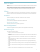
Figure 1-1 Logical overview of the Lustre file system Configuration Management Server Configuration information, network connection details, & security management Lustre Client Directory operations, meta-data & concurrency MDS Server File I/O & file locking Recovery, file status, file creation Object Storage Servers A typical Lustre file system consists of multiple Object Storage Servers that have storage attached to them.
All of the software that is needed to operate the HP SFS system is installed from the HP StorageWorks Scalable File Share System Software CD-ROM. You do not need to, nor should you, install any other software on an HP SFS system. 1.1.
• A server pair consisting of the administration server and the MDS server, and pairs of Object Storage Servers In the event of failure of the MDS server, the administration server is capable of taking over the function of serving file system meta-data (in addition to continuing to serve the administration functions). Similarly, in the event of failure of the administration server, the administration functions automatically fail over to the MDS server.
For more information about the topology of Object Storage Servers in systems using EVA4000 arrays, see Section 1.4.1. For information on configuring the storage on EVA4000 arrays, see Chapter 5. 1.1.3.2.2 SFS20 storage arrays An SFS20 storage array is a RAID array that can be attached to two servers. A system configured with SFS20 arrays is configured to have high availability, and Object Storage Servers are organized in pairs.
1.1.3.3 Network connections The servers in the HP SFS system are connected to networks inside and outside the system as follows: • The administration server and the MDS server each have a connection to the site network. The site network connection provides management access to the HP SFS system. • All servers within the HP SFS system are connected to the system interconnect (there can be a number of interconnects).
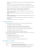
1.1.3.3.2 Management network Figure 1-6 shows how the servers in the HP SFS system are connected to the management network. Figure 1-6 HP SFS management network Site Network Admin 1 iLO MDS 2 iLO Management Network OSS iLO 3 OSS iLO 4 OSS iLO 5 OSS iLO OSS 6 iLO n-1 OSS iLO n Legend Admin: Administration Server MDS: Meta-data Server OSS: Object Storage Server iLO: Integrated Lights Out The management network is a private network.
1.3 Supported hardware Table 1-1 lists the supported hardware devices for HP SFS systems.
• One Fibre Channel connection from each controller to each switch (four connections in total). • Dual-port HBAs on each of two servers, one port connected to each switch. • EVA4000 storage presented to each of two servers on each of two controllers (preferred to one) and accessible on each of two HBA ports. Such a configuration can tolerate the following possible failures: • Failure of a single controller—peer controller can take over.
A configuration with less redundancy can be configured using one plane of Fibre Channel connectivity. This configuration consists of the following components: • One EVA4000 pair. • One 4GB Fibre Channel switch. • One Fibre Channel connection from each controller to the switch (two connections in total). • Dual-port HBAs on each of two servers, one port connected to each switch. • A Fibre Channel HBA on each of two servers, one port not connected.
1.4.2 Topology in systems using SFS20 storage arrays The SFS20 array is a serial ATA (SATA) 1.5 Gb/s disk drive storage array with Ultra320 SCSI host connectivity. The SCSI ports of each SFS20 array connect to Smart Array HBAs on each server. The array can contain up to 12 SATA drives configured with RAID5 or ADG redundancy, and presents storage to the Object Storage Servers over a SCSI interconnect.
1.4.2.1 Dual-connected SFS20 configuration A dual-connected SFS20 configuration consists of a pair of SFS20 arrays, each of which is connected to two servers. In normal operation, one server accesses one of the SFS20 arrays, while the other server accesses the second array. If one of the servers in the server pair fails, the other server accesses both SFS20 arrays. Figure 1-9 shows a dual-connected SFS20 configuration.
1.4.2.2 Mirrored dual-connected SFS20 configuration A mirrored dual-connected configuration consists of two pairs of SFS20 arrays, all of which are connected to both servers in an Object Storage Server pair. One of the servers accesses one of the SFS20 arrays and mirrors the data to a second SFS20 array. The second server does the same on a second pair of SFS20 arrays. Figure 1-10 shows a mirrored dual-connected SFS20 configuration.
1.5 Interconnect topology The interconnect types supported for use with HP SFS systems are as follows: • Gigabit Ethernet networks • Dual Gigabit Ethernet interconnect • Bonded Gigabit Ethernet interconnect • Quadrics interconnect • Myrinet interconnect • Voltaire InfiniBand interconnect Client nodes can access file system data on an HP SFS system using one of several supported network protocols.
• A client node connects to the HP SFS system using one and only one of the available protocols (that is, there is no capability to fall back to a Gigabit Ethernet interconnect from a fast interconnect and continue operation without interruption). However, a client node can unmount a file system and then remount it using a different protocol. • Client nodes cannot mount the same file system more than once at any one time using different protocols.
1.5.1.1 Voltaire InfiniBand interconnects In the general case where no special configuration is applied, all nodes connected to an InfiniBand interconnect can communicate with each other. At least one InfiniBand IP address (IPoIB address) must be configured on each server and on each client node. HP SFS and Lustre use the IPoIB address to form the Network ID (NID) and to establish connections with other nodes.
Figure 1-13 Bonded network configuration Client ethn /bondn Gigabit Ethernet Switch bond0 Admin bond0 MDS eth2 eth3 bond0 OSSn Legend Admin: Administration Server MDS: Meta-data Server OSS: Object Storage Server There are two supported configurations for dual Gigabit Ethernet connections: symmetric and asymmetric. For more information, see Section 2.4.2.
1.6 Hardware overview This section provides an overview of the supported hardware configurations for HP SFS systems, and is organized as follows: • Site, interconnect, and management network connections (Section 1.6.1) • HP ProLiant DL360 G4/G4p server (Section 1.6.2) • HP ProLiant DL380 G4 server (Section 1.6.3) • The management network (Section 1.6.4) • The Gigabit Ethernet interconnect (Section 1.6.5) • The dual Gigabit Ethernet interconnect (Section 1.6.
1.6.2 HP ProLiant DL360 G4/G4p server Figure 1-14 shows the rear view of an HP ProLiant DL360 G4/G4p server. Figure 1-14 HP ProLiant DL360 G4/G4p server — rear view (Optional) Interconnect adapter iLO Storage HBA NIC 1 NIC 2 Power cord connector USB The components and interfaces of the server that are used by the HP SFS system include the following: • The Integrated Lights Out (iLO) management port The iLO port is used to connect the iLO component in the server to the management network.
1.6.3 HP ProLiant DL380 G4 server Figure 1-15 shows the rear view of the HP ProLiant DL380 G4 server.
NOTE: Both the MDS server and the administration server are configured by default with 4GB of memory, while Object Storage Servers are configured with 2GB of memory. MDS servers benefit from the extra memory for highly meta-data-intensive workloads, and as the administration server is the failover server for the MDS server, it must have the same configuration.
1.6.5 The Gigabit Ethernet interconnect Figure 1-17 shows how ProLiant DL360 servers are connected to a Gigabit Ethernet interconnect. The Gigabit Ethernet switch is not part of the HP SFS system—you may choose your own switch technology. The switch shown in Figure 1-17 is for illustrative purposes only. Figure 1-17 shows a system using ProLiant DL360 servers; the connections in a system using ProLiant DL380 servers would be similar (subject to the rules defined in Section 2.4.1).
1.6.6 The dual Gigabit Ethernet interconnect Figure 1-18 and Figure 1-19 show how ProLiant DL360 servers could be connected to a dual Gigabit Ethernet interconnect. The Gigabit Ethernet switches are not part of the HP SFS system—you may choose your own switch technology. The switches shown in these figures are for illustrative purposes only.
1.6.7 The bonded Gigabit Ethernet interconnect Figure 1-20 shows how ProLiant DL360 servers could be connected for a bonded Gigabit Ethernet interconnect. The Gigabit Ethernet switch is not part of the HP SFS system—you may choose your own switch technology. The switch shown in this figure is for illustrative purposes only.
1.6.8 The Quadrics interconnect Figure 1-21 shows how ProLiant DL360 servers are connected to the Quadrics interconnect. The switches in the Quadrics interconnect and the connections to the client nodes are part of, and managed by, the client system. Figure 1-21 shows a system using ProLiant DL360 servers; the connections in a system using ProLiant DL380 servers would be similar (subject to the rules defined in Section 2.4.1).
1.6.9 The Myrinet interconnect Figure 1-22 shows how ProLiant DL360 servers are connected to the Myrinet interconnect. The switches in the Myrinet interconnect and the connections to the client nodes are part of, and managed by, the client system. Figure 1-22 shows a system using ProLiant DL360 servers; the connections in a system using ProLiant DL380 servers would be similar (subject to the rules defined in Section 2.4.1).
1.6.10The Voltaire InfiniBand interconnect Figure 1-23 shows how ProLiant DL360 servers are connected to the Voltaire InfiniBand interconnect. Figure 1-23 shows a system using ProLiant DL360 servers; the connections in a system using ProLiant DL380 servers would be similar (subject to the rules defined in Section 2.4.1).
1.6.11The EVA4000 storage array Figure 1-24 shows how EVA4000 arrays are connected to the storage array network (SAN). It also shows how ProLiant DL360 servers are connected to the storage arrays. Figure 1-24 EVA4000 storage array 2 x DL360 Fibre Switch Fibre Switch The configuration shown here consists of a pair of servers and their associated EVA4000 storage. This configuration corresponds to two Object Storage Servers and their associated EVA4000 storage.
1.6.12The SFS20 storage array Figure 1-25 shows how SFS20 storage arrays are connected to ProLiant DL380 servers. Figure 1-25 SFS20 storage array B1 B2 A1 A2 DL380 B1 B2 A1 A2 DL380 SFS20 Enclosure SFS20 Enclosure SFS20 Enclosure SFS20 Enclosure The configuration shown here consists of a pair of servers and their associated SFS20 storage. This configuration corresponds to two Object Storage Servers and their associated SFS20 storage.
connected to the adapter in the same PCI slot on each of the servers. If the connections for a given SFS20 storage array are not symmetrical, the configure server command reports this when the storage is being configured. The Smart Array 6404 adapter has four ports. These ports must be populated in the following order: A1, A2, B1, B2; that is, connect the first SFS20 array to port A1, the second to port A2, and so on.
1–32 Overview
2 Preparing for the installation This chapter describes the preparations you need to make and the information you need to gather before you install and configure your HP SFS system software. The chapter is organized as follows: • Before you start (Section 2.1) • Setting up access to the servers (Section 2.2) • Planning system information (Section 2.3) • Planning the networks (Section 2.4) • Planning the connection to the site network (Section 2.
2.1 Before you start Before you start to plan your installation, read the HP StorageWorks Scalable File Share Release Notes, which describe any late changes and known problems in the HP SFS system software. 2.2 Setting up access to the servers To configure certain settings on the servers at the start of the installation process, you must have physical access to the servers. 2.
• The DNS domain name of the system. An example DNS domain name is my.domain.com. Server host names use the fullname form. For example, the host name of the first server in the south system is south1.my.domain.com. Unlike the system name, which becomes fixed once you start the software installation process, you can change the DNS domain name at a later stage. • The number of servers in the system.
• • If your system is using a Quadrics interconnect, perform the following tasks: 1. Assign ports on the Quadrics interconnect (see Section 2.4.4). 2. Determine the Quadrics machine ID (see Section 2.4.5). If your system is using a Myrinet interconnect, assign ports on the Myrinet interconnect (see Section 2.4.6). The Configure Networks menu is used to access the menus for entering network information during installation (see Section 6.8.2 or Section 7.4.2, depending on the type of storage used). 2.
There are a number of configurations for the site connections and the networks that are allowed by these rules, and these configurations are described here. Configuration 1 A dedicated Quadrics, Myrinet, Voltaire InfiniBand, or a dual or bonded Gigabit Ethernet interconnect is used. The site network is not an interconnect. Figure 2-1 shows the connections in this configuration when a dedicated Myrinet, Quadrics, or Voltaire InfiniBand interconnect is used.
• • On ProLiant DL360 servers, the PCI slots are used as follows: • A Myrinet, Quadrics, Voltaire InfiniBand, or Dual Port PCI-X Gigabit Ethernet adapter is used in the first PCI slot on all servers for the connection to the interconnect. • The second PCI slot on each server is always used for connection to storage.
Configuration 3 Two interconnects are used: one is a Quadrics, Myrinet, or Voltaire InfiniBand dedicated interconnect, the other is a single Gigabit Ethernet interconnect. Neither a dual nor a bonded Gigabit Ethernet interconnect can be used in this configuration. The Gigabit Ethernet interconnect is also used as the external connection for the administration and MDS servers.
Configuration 4 A single Gigabit Ethernet interconnect is the sole interconnect and the Gigabit Ethernet connection is also used as the external connection for the MDS and administration servers.
Configuration 5 A dedicated single Gigabit Ethernet interconnect is used. The interconnect does not have a connection to the site network. Figure 2-6 shows the connections in this configuration. Figure 2-6 Configuration 5—Single Gigabit Ethernet interconnect and separate site network In this configuration, the connections are as follows: • NIC 1 on all of the servers in the HP SFS system is connected to the management network. • NIC 2 on all servers is connected to the interconnect.
2.4.2 Assigning IP addresses on Gigabit Ethernet networks NOTE: Use the worksheet in Table B-2 in Appendix B to record the information you gather in this section. You can have up to three Gigabit Ethernet networks in an HP SFS system. Only two of these networks can be used as interconnects, and the administration server and the MDS server must use one of the Gigabit Ethernet networks to connect to the site network (for system administration purposes). As described in Section 2.4.
CAUTION: With the exception of bonded Gigabit Ethernet interfaces, each Gigabit Ethernet interface must be on a separate logical network. • The maximum transfer unit (MTU) of the network interface. HP recommends that you use the default of 1500 for all Gigabit Ethernet interfaces, and in the case of using a bonded Gigabit Ethernet interconnect, you must use an MTU of 1500. • If you want to configure static routing on the network, you will need to specify the static routes.
2.4.2.1 Gigabit Ethernet interconnect considerations The NIC 2 port on a server is used to connect the server to the Gigabit Ethernet switch. While performance or logistics concerns may dictate specific Gigabit Ethernet port assignments, how the ports are assigned is of no consequence to the HP SFS system. Provided that all server and client ports are on the same physical or virtual LAN, the HP SFS system will logically behave in the same way.
There are two supported configurations for the use of multiple Gigabit Ethernet links: • Symmetric: Dual server links with dual client node links (see Section 2.4.2.2.1) • Asymmetric: Dual server links with single client node links (see Section 2.4.2.2.
2.4.2.2.1 Symmetric dual Gigabit Ethernet network configuration In a symmetric configuration, the number of interconnect interfaces per server and the number of interconnect interfaces per client node are the same. In this case, the simplest way of configuring the networks is to use a separate network for each link and to ensure that the networks cannot intercommunicate. Dual-link server to dual-link client nodes configuration Figure 2-7 shows a very simple setup for a symmetrical configuration.
Figure 2-8 shows an example of a dual-link server to dual-link client node network where the networks are not physically separate.
2.4.2.2.2 Asymmetric dual Gigabit Ethernet configuration All configurations where there are more interfaces on the HP SFS servers than there are on the client nodes are asymmetric configurations. Asymmetric configurations are more complicated than symmetric configurations because it is not possible to logically split the networks and still retain full connectivity between all systems.
Figure 2-10 Incorrect physical HP SFS connections in dual-link server to single-link client nodes configuration In the configuration shown in Figure 2-10, client nodes 7 through 12 will typically all be able to perform I/O operations at the same time, to the limit of the network interfaces (in this case 600 MB/sec).
Recommendations: • If possible, do not use routers in the network between client nodes and servers; using routers in the network may impact performance adversely. • If your switch allows it, give your client nodes sequential MAC addresses for Gigabit Ethernet interconnect interfaces. For many switch types, this results in the most even balance between server slave devices and reduces the possibility of one server link being significantly more heavily loaded than others. 2.4.
• The client nodes join the private partition they belong to and also join the default partition using a Limited Membership key. • A single IPoIB interface is configured on the HP SFS servers, and two interfaces are configured on each client node. Note that this configuration is not supported for HP XC systems. • Using the private partitions for the HP SFS traffic. In such a configuration: • • The client nodes only join the private partition they belong to.
Table 2-1 Configuration 1—Partition table at the switch Host Pkey0 Pkey1 Sfs1 0xffff N/A Sfs2 0xffff N/A HostA1 0x7fff 0x8001 HostA2 0x7fff 0x8001 HostB1 0x7fff 0x8002 HostB2 0x7fff 0x8002 Table 2-2 shows how the IPoIB interfaces could be configured where one network is configured for each partition. Table 2-2 Configuration 1—IPoIB interfaces where one network is configured for each partition Hosts ipoib0 Pkey ipoib1 IP Mask Pkey IP Address Mask Sfs1 0xffff 172.32.0.1 255.
2.4.3.1.2 Configuration 2—using the private partitions for the HP SFS traffic In this configuration, the HP SFS traffic uses all of the private partitions; therefore, the HP SFS servers need to join all partitions. Note that in this configuration: • The nodes in cluster A cannot communicate with the nodes in cluster B. • The nodes in cluster A and the nodes in cluster B can communicate with the HP SFS servers. Table 2-4 shows the partition table at the switch.
Table 2-6 Configuration 2—IPoIB interfaces where a single network is shared by multiple partitions Hosts ipoib0 Pkey IP ipoib1 Mask Pkey IP Address Mask Sfs1 0x8001 172.32.0.1 255.255.255.128 0x8002 172.32.0.129 255.255.255.128 Sfs2 0x8001 172.32.0.2 255.255.255.128 0x8002 172.32.0.130 255.255.255.128 HostA1 0x8001 172.32.0.3 Default N/A N/A N/A HostA2 0x8001 172.32.0.4 Default N/A N/A N/A HostB1 0x8002 172.32.0.131 Default N/A N/A N/A HostB2 0x8002 172.32.0.
Table 2-8 Configuration 3—IPoIB interfaces where one network is configured for each partition Hosts ipoib0 Pkey IP ipoib1 Mask Pkey IP Address Mask Sfs1 0xffff 172.32.1.3 Default 0x8001 172.32.2.3 Default Sfs2 0xffff 172.32.1.4 Default 0x8001 172.32.2.4 Default HostA1 0x8001 172.32.1.1 Default N/A N/A N/A HostA2 0x8001 172.32.1.2 Default N/A N/A N/A NFShost1 0xffff 172.32.1.5 Default N/A N/A N/A NFShost2 0xffff 172.32.1.
• If the InfiniBand interconnect is partitioned, you may define multiple interfaces (one for each partition where the HP SFS system will be used) and you have the facility to provide a Pkey value for each interface. The InfiniBand network information is entered at the Configure InfiniBand Interconnect menu during installation (see Section 6.8.2.3 or Section 7.4.2.3, depending on the type of storage used). 2.4.
2.5 Planning the connection to the site network NOTE: Use the worksheet in Table B-5 in Appendix B to record the information you gather in this section. You need to identify the following site network information, which you will supply when you are installing your HP SFS system: • The IP address of the default gateway router. Use the IP address of a router on your site network.
2.6 Planning the management network IP addresses NOTE: Use the worksheet in Table B-6 in Appendix B to record the information you gather in this section. The management network is a dedicated, private network that connects all servers in the HP SFS system. As the network is a private network and is not connected to any other network, you usually do not need to change the system default configuration.
2.8 Assigning roles to servers NOTE: Use the worksheet in Table B-7 in Appendix B to record the information you gather in this section. Within an HP SFS system, various servers are responsible for running specific services, as follows: Administration The administration service allows you to configure and operate the HP SFS system and to configure the file systems served by the HP SFS system. The server the administration service runs on is referred to as the administration server.
Configurations (b) and (d) each have eight OST services. However, configuration (b) has fewer servers, and this may lead to lower performance. The administration and MDS services may also have a performance impact—this is determined by the access patterns of the file systems 2.9 Assigning storage arrays to servers NOTE: The tasks associated with storage planning and configuration are described in Chapter 5 (EVA4000 and SFS20 storage) and Chapter 7 (SFS20 storage only).
2.10 Choosing the root user password When the HP SFS software is installed, the servers are configured with the password for the root user set to secret. Instructions are provided in the relevant sections for changing this password. HP strongly recommends that you change the root user password. When choosing a new password, consider the following points: • Do not keep the default secret password. • Do not use words from the dictionary.
Following are three examples of license files that you may receive from HP. Example 2-1 License file 1 SERVER this_host ANY USE_SERVER VENDOR HPQ INCREMENT SFSMDSCAP HPQ 1.0 permanent 1 HOSTID="000bcd505cbb \ 000bcd827644" NOTICE="License Number 7YCYHDHTEYAH" \ SIGN=F3D03152BE24 Example 2-2 License file 2 SERVER this_host ANY USE_SERVER VENDOR HPQ INCREMENT SFSOSTCAP HPQ 1.
• The HOSTID field shows the license host IDs of the administration and MDS servers (which you will identify during installation). • The NOTICE field contains the license number that is printed on the License-To-Use letter sent to you by HP when you order the license. This allows you to match increment lines with the corresponding licenses that you have purchased. • The SIGN field contains a checksum of all the other values in the INCREMENT line. INCREMENT SFSOSTCAP HPQ 1.
2–32 Preparing for the installation
3 The sfsmgr utility This chapter provides an overview of the sfsmgr(8) utility, and is organized as follows: • Overview (Section 3.1) • Starting the SFS CLI (Section 3.2) • Running sfsmgr commands (Section 3.3) • Troubleshooting the sfsmgr command (Section 3.
3.1 Overview The HP SFS system is not a general purpose system; instead, it is dedicated to running MDS and OST services. Unless instructed to do so by your HP Customer Support representative, do not install any software package on the system. Such action is not supported and may impact the correct operation of the system. The HP SFS system is managed and operated through the sfsmgr(8) utility. All changes to system configuration or server configuration are executed by this utility.
When you first enter the sfsmgr command when installing or upgrading a system, the output displayed is one of the following: • If the system software has never been installed, either at the factory or on site, the following menu is displayed. Enter 1 to select the option to install the system: # sfsmgr . . .
You must enter enough letters to make the abbreviated command unique; if you do not, the command will not work (the usage for the command will be displayed). For example, in the show commands, you cannot abbreviate the word show to sh, as this could be confused with the shutdown command; you can, however, abbreviate it to sho. Similarly, you can abbreviate the show lun and the show log commands to sho lu and sho lo. 3.3.
========================= H e a r t b e a t S t a t u s ================== Name Type Status ------------------------------ ---------- -----------south1 <--> south2 network ONLINE ========================= S e r v i c e S t a t u s ====================== Last Service Status Owner Transition -------------- -------- -------------- ---------------admin started south1 10:49:09 Aug 04 Monitor Interval -------30 Restart Count ------0 Under normal circumstances, the status of the administration service
3–6 The sfsmgr utility
4 Configuring a factory-installed system This chapter describes how to configure a system that has had the HP SFS software installed before the system was delivered to your site. If your system was not factory-installed, proceed to Chapter 6 (if your system uses EVA4000 storage) or to Chapter 7 (if your system uses SFS20 storage) to install the system. When a system is factory-installed, all hardware is configured, the software is installed, and all components are tested.
4.1 Step 1: Gathering system information During the installation process, you will be required to supply a number of items of system information. HP strongly recommends that you have this information ready before you start the installation. Chapter 2 describes how to define and identify the required information. 4.
Enter your choice [a]: 1 Configure Gigabit Ethernet Networks -------------------------------------------This section is used to configure the Gigabit Ethernet networks, excluding the Management Network. If configured on all servers, these networks can be used as an interconnect to client systems. If not configured on all servers, these networks are only configured on the Administration and MDS servers and are used to connect to your site network.
servers are assigned an IP address by incrementing this IP address. Enter the Start IP (e.g. 1.2.3.4 or None) [10.128.0.11]: 16.123.123.1 Enter the Netmask [255.255.255.0]: Enter the MTU [1500]: Enter the static routes in the form: ,,; ... For example to add the following two static routes: network 10.10.0.0, netmask 255.255.0.0, gateway 10.128.8.1 network 10.0.0.0, netmask 255.255.0.0, gateway 10.64.0.1 Enter the following: 10.10.0.0,255.255.0.0,10.128.8.1;10.0.0.0,255.255.0.
6. Enter c to exit from the menu, and then enter c again to exit from the Configure Networks menu, as shown in the following example: Enter your choice [a]: c Configure Networks ------------------------------------------------------------This section is used to configure Gigabit Ethernet, InfiniBand and Quadrics networks on all servers. These networks are used as interconnects to client systems. If you do not have a Gigabit Ethernet / InfiniBand / Quadrics interconnect you can proceed to the next section.
Specify the IP address of the router on your site network. Enter the Gateway IP (e.g. 1.2.3.4 or None) [None]: 16.123.123.250 Specify the IP address of a DNS server. Enter the DNS server (1) (e.g. 1.2.3.4 or None) [None]: 16.123.123.250 Enter the DNS server (2) (e.g. 1.2.3.4 or None) [None]: Enter the IP address of an NTP server. If DNS is configured it may be appropriate to enter the hostnames of the NTP servers rather than their IP addresses.
8. Enter e to save your changes as follows: . . . e) Exit (save updates) q) Quit (discard updates) Enter your choice [a]: e 9. Reconfigure the networking configuration on the administration server, by entering the command shown in the following example (where south1 is the administration server): sfs> configure server south1 redo=Clusterized 10.
• If the interconnect was reconfigured since leaving the factory (for example, if the port used on the Quadrics interconnect has changed), you cannot perform any test that requires the presence of a file system. This is because reconfiguring the interconnect breaks the file system configuration, and the file system configuration will not be repaired until the upgrade has been completed.
4.5.2 Reinstalling the HP SFS system software Before you start to reinstall the HP SFS system software, examine the output from the show array array_number command to determine if the arrays are correctly configured to meet your needs. For example, if you plan to use more than one file system, the arrays connected to the administration and MDS servers (and used for MDS LUNs) may not be configured appropriately (that is, they may not have enough LUNs).
4–10 Configuring a factory-installed system
5 Configuring the storage NOTE: If your HP SFS system was installed at the factory, the storage will have been configured (in a standard configuration) and you may not need to perform any of the tasks described in this chapter. However, this chapter contains information on storage concepts and parameters that you may find useful when operating your system.
5.1 EVA4000 storage — overview and planning This section contains a description of EVA4000 storage concepts and provides some examples to help you to plan your storage configuration. This section is organized as follows: • EVA4000 storage concepts (Section 5.1.1) • EVA4000 configuration rules for HP SFS systems (Section 5.1.2) • Assigning and sizing LUNs on EVA4000 storage (Section 5.1.3) 5.1.
Logical Units (LUNs) and Virtual Disks A virtual disk is a storage subdivision that is allocated from some of the available capacity of a disk group. When a virtual disk is created on an EVA4000 array, it is assigned a 32–character WWID that is unique across all RAID arrays from any vendor. A virtual disk cannot be accessed by a server until it is presented to the server. When the virtual disk has been presented to a server, the virtual disk is called a logical unit (LUN).
is used to store data. Replace the failed disk as soon as possible, because a subsequent disk failure may cause you to lose access to data. • The total size of the LUNs in a disk group must occupy less than 90% of the available capacity of the disk group. This limit applies to the actual capacity of the disk group, not the raw capacity of the disks in the disk group. The actual capacity is much lower than the raw size of the disks due to disk sparing.
Administration LUN The administration LUN is used to store configuration information for the HP SFS system. There is only one administration LUN for the whole system, and it must be created on the EVA4000 array that is connected to the administration and MDS servers. In the HP SFS user interface, the administration LUN is identified as the adm LUN. Service LUN Service LUNs are used to store management data and control data for a pair of servers. There is one service LUN for each server pair.
• HP recommends that you make your OST LUNs as large as possible. However, as explained in Section 5.1.2, if a service LUN or an MDS LUN already exists in a disk group, the OST LUNs must be sized so that the total used size is 90% of the total capacity of the disk group. Role The role of the LUN is one of the following: • adm — the administration LUN • service — a service LUN • mds — an MDS LUN • ost — an OST LUN LUN roles are described in Section 5.1.3.1.
5.1.3.2.2 EVA4000 configuration example 2 — small system Table 5-2 shows how to configure LUNs in a system comprised of four servers and four EVA4000 arrays. In this configuration, you can create a file system comprised of one MDS service and eight OST services. This configuration assumes that servers south[1-2] run OST services in addition to running the MDS service.
5.1.3.2.3 EVA4000 configuration example 3 — larger system Table 5-3 shows how to configure LUNs in a system comprised of six servers and five EVA4000 arrays. In this configuration, you can create a file system comprised of one MDS service and eight OST services. In this example configuration, the MDS service runs on a dedicated MDS server (south2). Table 5-3 Larger system example Array Disk Group Size 1 1 2 3 4 5 Role Presented to Notes 40GB1 adm south[1-2] The administration LUN.
5.1.3.2.4 EVA4000 configuration example 4 — multiple file systems Table 5-4 shows how to configure LUNs in a system comprised of six servers and five EVA4000 arrays. In this configuration, you can create two file systems. The first file system is comprised of one MDS service and six OST services. The second file system is comprised of one MDS service and two OST services.
5.2 Configuring EVA4000 storage This section describes the tasks you must perform to configure the EVA4000 storage to the point where the virtual disks have been created. The remaining storage configuration steps (creating hosts and presenting virtual disks to the hosts) are performed as part of the installation process, described in Chapter 6. You must use a Microsoft® Windows® server to configure and manage the EVA4000 storage arrays; the server must have the Command View EVA application installed on it.
Each switch requires its own IP Address. Give the first switch the address 192.168.32.1, the second switch the address 192.168.32.2, and so on. The switches will then be accessible from the servers using the telnet(1) command, as shown in the following example: # telnet 192.168.32.1 5.2.3 Initializing the EVA4000 storage arrays The EVA4000 storage arrays must be initialized (through the Command View EVA application) before they can be configured.
5.2.4.2 Step 2: Identifying EVA4000 array WWIDs When you later install and configure the HP SFS system (as described in Chapter 6), the system discovers which EVA4000 arrays are connected to the system’s servers. The system can identify arrays using their WWID. In addition, as described in Section 5.1.1, the system assigns a unique number to each EVA4000 array as it is discovered.
• Redundancy level. In an HP SFS system, you must use the RAID5 redundancy level on EVA4000 arrays. The overhead required to support this level of redundancy reduces the available capacity by a further 20%. For example, in a disk group where the available capacity is 315GB, using RAID5 redundancy reduces the available capacity to 252GB. • Number of virtual disks being created in the disk group.
2. Create the virtual disks, as shown in the following example. In this example, three virtual disks are created on the first array in the system, one to be used as a service LUN and two to be used as OST LUNs.
To connect to the Microsoft Windows server, perform the following steps: 1. Start a Web browser and enter the IP address of the Microsoft Windows server where Command View EVA is installed, for example: http://16.123.123.30 A Web interface to the server is displayed. Figure 5-1 shows the interface. Figure 5-1 Storage management Web interface 2. Click the Devices link, and then click the Command View EVA link.
5.2.5.2 Step 2: Recording EVA4000 array WWIDs When you later install and configure the HP SFS system (as described in Chapter 6), the system discovers which EVA4000 arrays are connected to the system’s servers. The system can identify arrays using their WWID. In addition, as described in Section 5.1.1, the system assigns a unique number to each EVA4000 array as it is discovered.
5.2.5.4 Step 4: Creating virtual disks The size of the virtual disks that you can create depends on a number of factors, including the following: • Capacity of the disk group You cannot allocate more than 90% of the total capacity of the disk group, and the Command View EVA Web interface enforces this rule. For example, if the disk group has a total capacity of 350GB, the maximum size for a virtual disk in the disk group is 315GB (that is, 90% of 350GB).
Figure 5-4 Create a Vdisk Family page The name that you enter on this page is the name given to the virtual disk family. The Active member of a virtual disk family is the virtual disk that is accessed by one or more servers for storage. The Active member of a virtual disk family and its snapshot, if one exists, constitute a virtual disk family. The two OST virtual disks on the array must be in different disk groups, and preferred to different controllers.
5.3 SFS20 storage — overview and planning The SFS20 array is a serial ATA (SATA) 1.5 Gb/s disk drive storage array with Ultra320 SCSI host connectivity. It has two ports and can be connected to two servers. The administration and MDS server pair can be connected to up to a maximum of four SFS20 arrays, while an Object Storage Server pair can be connected to up to a maximum of eight SFS20 arrays. You will configure the SFS20 storage during the system installation.
5.3.2 LUN roles The primary purpose of the storage arrays is to store the Lustre file system data. However, the HP SFS system also uses some storage to manage the system. When you configure the system, you use LUNs for each of these different purposes, as follows: MDS LUN MDS LUNs are used to store the meta-data for a Lustre file system. In HP SFS systems, you must create two MDS LUNs for each file system.
5.3.3 ADG and RAID5 redundancy This section compares the basic hardware RAID capabilities of a single SFS20 array and describes the issues that need to be taken into account when you are determining which type of RAID redundancy to use. NOTE: To maximize data integrity and simplify disk replacement, HP recommends that SFS20 arrays in new customer installations are configured with ADG (RAID 6) redundancy.
• Capacity Each SFS20 array has twelve SATA disks of varying capacities. Depending on the size of disk used, the type of redundancy affects the capacity as follows: • In configurations where 160GB disks are used, all disks can be used in the case of both ADG and RAID5 redundancy. In such configurations, the largest possible LUN when ADG redundancy is used is smaller by one disk than the largest possible LUN when RAID5 redundancy is used.
• There must be two MDS LUNs for each file system, one on each of two arrays attached to the MDS and administration server. This configuration is required to support mirrored LUNs. • You can configure the SFS20 arrays with either ADG or RAID5 redundancy (see Section 5.3.3 for more information). • The best performance is obtained from a single disk group populated with as many disks as possible. The default disk group size is eleven disks.
Table 5-5 SFS20 arrays attached to the administration and MDS servers — one file system Array 2 Disk Group Size Role 1 Connected to Notes 1 40GB admspare south[1-2] The spare administration LUN. 1 1GB svcspare south[1-2] A spare service LUN for the south1 and the south2 server pair. 1 mds All of the remaining capacity in the disk group to a maximum of 2TB. south[1-2] The second of the pair of LUNs for the MDS service. 1. Can be configured to a different size.
Table 5-6 SFS20 arrays attached to the administration and MDS servers — two file systems Array 2 Disk Group Size Role 1 Connected to Notes 1 40GB admspare south[1-2] The spare administration LUN. 1 1GB svcspare south[1-2] A spare service LUN for the south1 and the south2 server pair. 1 33% of the remaining capacity in the disk group. mds south[1-2] The second of the pair of LUNs for the MDS service in one of the file systems.
• The number of OST LUNs that can be used by a server is limited by the number of LUNs that the Smart Array 6404 adapter can work with. Each Smart Array 6404 adapter has two controllers, and each controller can work with 16 LUNs. This means that a maximum of 32 LUNs can be used on the arrays connected to the Smart Array 6404 adapter (that is, 16 per controller). This limit is unlikely to be reached in normal operation; HP does not recommend the use of large numbers of small LUNs in HP SFS systems.
Table 5-8 shows details of the resulting configuration on two arrays attached to an Object Storage Server pair (south3 and south4). Table 5-8 SFS20 arrays attached to Object Storage Servers Array Disk Group Size Role Connected to Notes 3 1 1GB service south[3-4] The service LUN for the south3 and south4 server pair. 1 ost All of the remaining capacity in the disk group to a maximum of 2TB. south[3-4] The first OST LUN.
Table 5-9 shows an example configuration of a system with two servers and two arrays after the set lun command has been used to change the LUN roles to ost. In this system configuration, you can create a file system comprised of one MDS service and four OST services. Table 5-9 Minimal system — two servers and two arrays Array 1 2 Disk Group Size Role Connected to Notes 1 40GB1 adm south[1-2] The administration LUN.
5.4 Configuring SFS20 storage You do not need to preconfigure the SFS20 arrays; all SFS20 storage is configured during system installation, when you install the servers. Proceed to Chapter 7 to install and configure the servers. 5.5 MDS LUN sizing guide The size of the MDS LUNs used for a file system determines the number of files that the file system can hold.
CAUTION: Once a file system is created, the ratio of objects to storage cannot be changed without recreating the file system. NOTE: All storage capacities discussed here are based on the size of the LUNs as presented to the MDS server and the Object Storage Servers, and not on the raw aggregate capacity of the disks on a storage array. The conversion from raw capacity to storage is dependent on the storage technology chosen.
6 Installing the servers — EVA4000 storage NOTE: All of the software that is needed to operate the HP SFS system is installed from the HP StorageWorks Scalable File Share System Software CD-ROM. You must not install any other software on the HP SFS system, unless instructed to do so by HP. Installing other software is unsupported. This chapter provides step-by-step instructions for installing an HP SFS system that uses EVA4000 storage.
6.1 Step 1: Gathering system information During the installation process, you will be required to supply a number of items of system information. Before you start the installation, make sure that you have this information ready. Chapter 2 describes how to define and identify the required information; please ensure that you have read Chapter 2 before you start to install your system. 6.2 Step 2: Zoning the Fibre Channel fabric You must zone the Fibre Channel fabric as described here.
CAUTION: If you fail to ensure that the firmware versions on the servers are correct (as detailed in the HP StorageWorks Scalable File Share Release Notes), or if you fail to set a configuration parameter as described in this section, there will be problems operating the HP SFS system. Such problems can range from inability to perform management functions to system instability and server crashes. 6.4.
6.4.3 iLO settings — iLO browser tasks NOTE: To complete the configuration of the iLO settings on the servers, you must connect a Linux system or a Microsoft® Windows® PC running a Web browser (Mozilla or Microsoft Windows Internet Explorer) to the management network. You now need to finish configuring the iLO settings and verify that you can access the iLO component of each server, as follows. Repeat these steps for each server: 1.
6. On the servers that will be the Object Storage Servers, set the Standard Boot Order (IPL) parameter to the following: 1. 2. 3. 4. CD-ROM Floppy PCI Embedded Gigabit Server Adapter Port 1 Hard Drive 7. Set the Server Availability/POST F1 Prompt parameter to Delayed. 8. Select the BIOS Serial Console/EMS Support option and set the EMS Console parameter to COM2, IRQ3. 9. Set the Advanced Options/Processor Hyper-Threading parameter to Disabled. Before proceeding to Step 3 (Section 6.
6.4.4.1 Upgrading server firmware offline using a USB pen drive NOTE: ProLiant DL G3 servers do not support a USB pen drive; if you are upgrading the firmware on a ProLiant DL G3 server, see Section 6.4.4.2. You can use a USB pen drive to upgrade the HP Integrated Lights-Out Management Controller firmware or the BIOS - System ROM firmware offline, as follows 1. Download the HP Drive Key Boot Utility from the following location: http://h18000.www1.hp.com/support/files/serveroptions/us/download/21621.
closed with the CD-ROM still in place; if this happens, the server will attempt to boot from CD-ROM the next time it is booted. Proceed to Section 6.6 to create an EVA4000 host entry for the administration and MDS servers. 6.6 Step 6: Creating an EVA4000 host entry for the administration and MDS servers To allow a server to have access to a virtual disk, you must present the virtual disk as a LUN to the HBA ports on the server.
CAUTION: When you create the host entry, you must set the OPERATING_SYSTEM value to UNKNOWN, as shown in the following example. If the OPERATING_SYSTEM value is set to anything other than UNKNOWN, the storage array will be unusable.
6. On the Add a Host Port page, enter the WWID of the second HBA port on the administration server, then click the Add port button. Figure 6-2 shows the Add a Host Port page. Figure 6-2 Add a Host Port page If the administration and MDS server pair have access to a second EVA4000 array, repeat these steps to create an entry for the server pair on that array also. Proceed to Section 6.11 to present virtual disks to the administration server. 6.
NOTE: The LUN numbers that you use in the ADD LUN command are unique only within the array. They do not correspond to the LUN numbers across the system. Repeat these commands as necessary to present the required virtual disks to the server pair. When you have finished presenting the LUNs to the administration server, reboot the administration server by entering the following command on the administration server: # shutdown -r now Proceed to Section 6.12 to configure the system parameters.
2. Start the SFS CLI by entering the following command: # sfsmgr 3. If the system software has never been installed, either at the factory or on site, the following menu is displayed: . . . 1) Install new system (create new adm LUN) c) Cancel If the system software has previously been installed, either at the factory or on site, the following menu is displayed: . . .
4) 5) 6) a) e) q) Management Network iLO Access Storage All of the above Exit (save updates) Quit (discard updates) Enter your choice [a]: When working through the menus, note the following points: 6. • When you are configuring your system for the first time, it is best to accept the default menu option of a (All of the above), and work through the menus as they are displayed. You must enter the system and the network data at this time, but you have the option of entering other data at a later time.
Example 6-1 System menu example System ------------------------------------------------------------This section specifies the name of the system and the number of servers currently present. 1) 2) 3) 4) 5) System name DNS domainname Number of servers Number of the Admin (first) server Timezone south my.domain.com 4 1 EST5EDT When you have finished entering the system information, proceed to Section 6.8.2 to enter the interconnect information. 6.8.
If your system uses a Myrinet interconnect only, no configuration is needed. When you have configured the interface for your site network, select the Next Section option, and proceed to Section 6.8.3. • 6.8.2.1 Configuring Gigabit Ethernet networks CAUTION: If more than one Gigabit Ethernet network is used, each interface must be on a separate logical network. (In some cases, the networks may also be physically separate, but this is not a requirement.
Example 6-4 Network Device menu Network Device (eth1) ---------------------------------------------------------This section is used to configure a Network Device. The Start IP is the IP assigned to the Administration server. The addresses of the remaining servers are determined by incrementing the address of the Administration server. An alias IP can be configured on the network.
Type of network Start IP Netmask MTU Static Routes Alias IP Configure the network device on all servers tcp 16.123.123.101 255.255.255.0 1500 None 16.123.123.120 yes Is this correct? [yes]: Configure Gigabit Ethernet Networks -------------------------------------------This section is used to configure the Gigabit Ethernet networks, excluding the Management Network. If configured on all servers, these networks can be used as an interconnect to client systems.
Example 6-5 shows an example of configuring a bonded Gigabit Ethernet interconnect. In this example, three Gigabit Ethernet networks are detected and are unused. The example shows how to create a bonded network, using Gigabit Ethernet network devices eth2 and eth3 as slave devices. Note that eth2 and eth3 are the only devices that can be bonded.
Note that component devices of a bonded network are automatically assigned a network type of slave. This value should not be changed. Enter the Type of network [tcp]: Enter the slave devices as a comma separted list of eth devices. The available ethernet devices are: eth1,eth2,eth3 Enter the Slave devices (e.g. eth2,eth3) [None]: eth2,eth3 Once you specify the IP address of the Admin server the remaining servers are assigned an IP address by incrementing this IP address. Enter the Start IP (e.g. 1.2.3.
NOTE: The attributes of bonded Gigabit Ethernet interconnects are stored in the bonding_options attribute. If there is more than one bonded network, the attributes are common to all bonded networks.You can change these attributes after the system is installed. Refer to Chapter 7 of the HP StorageWorks Scalable File Share System User Guide for more information. 6.8.2.
n) Next Section p) Previous Section c) Cancel Enter your choice [a]: Valid network types are: vib The vib value is valid for the InfiniBand Interconnect Enter the Type of network [vib]: Once you specify the IP address of the Admin server the remaining servers are assigned an IP address by incrementing this IP address. Enter the Start IP (e.g. 1.2.3.4 or None) [None]: 172.32.0.1 Enter the Netmask [255.255.255.
To add a new IB Interface, enter 2 on the Configure InfiniBand Interconnect menu. When prompted, enter the information for the new InfiniBand interface that you gathered in your preinstallation planning in Section 2.4 and recorded in the worksheet in Table B-3. Example 6-7 shows an example of configuring an InfiniBand interface (ipoibN). Example 6-7 Add IB Interface menu. Add IB Interface (ipoibN) -----------------------------------------------------This section is used to add a new InfiniBand Interface.
6.8.2.5 Configuring Quadrics interconnects To configure a Quadrics Interconnect, enter a on the Configure Quadrics Interconnect menu to select the All of the above option. When prompted, enter the Quadrics Machine ID (identified in your preinstallation planning in Section 2.4 and recorded in the worksheet in Table B-4). Example 6-8 shows the Configure Quadrics Interconnect menu.
6.8.4 Entering management network information The management network is a dedicated, private network that connects all servers in the HP SFS system. The Management Network menu presents default parameters for this network, which you can normally accept. However, if your site network or Gigabit Ethernet interconnect already uses the 192.168 subnet, you will need to change the parameters for the management network. In such cases, HP recommends that you use the 10.0 subnet for the management network.
6.8.6 Entering storage information Use the Storage menu to confirm that the storage in your system supports high availability; that is, the storage attached to each server can also be accessed by the second server in the server pair. EVA4000 storage supports high availability, and you must accept the default of yes to confirm that shared storage is to be used for the administration and MDS server pair, and for the Object Storage Server pairs.
6.11.1Identifying administration and service LUNs for the administration server To identify the administration LUN and the service LUN for the administration server, perform the following steps: 1. Display details of the LUNs that have been presented to the administration server, as shown in the following example: sfs> show lun LUN --1 2 3 4 5 6 . . .
6.11.2Completing the configuration of the administration server To complete the configuration of the administration server, perform the following steps: 1. Enter the command shown in the following example: sfs> configure server south1 This command configures the system automatically, by giving the server a name, configuring the network interfaces, and configuring and starting cluster services including the administration (admin) service.
3. If the administration server is a ProLiant DL G4 server, skip this step. If the administration server is a ProLiant DL G3 server, reboot the administration server by entering the following command: # reboot Proceed to Section 6.12 to back up the system database. 6.12 Step 12: Backing up the system database At this point, back up the system database by entering the following command: sfs> create database_backup Proceed to Section 6.13 to scan the Media Access Control (MAC) addresses. 6.
4. Install the MDS server by entering the following command: boot: install When the installation process has completed, the server reboots automatically. NOTE: When the MDS server reboots, it is automatically configured; that is, you do not need to enter the configure server command. 5. When the server has rebooted, the installation CD-ROM is automatically ejected from the disk drive. Remove the CD-ROM from the disk drive tray.
To complete the presentation of virtual disks to the MDS server, perform the following steps: 1.
3. Start the MDS server again by entering the command shown in the following example: sfs> boot server south2 4. Enter the command shown in the following example: sfs> configure server south2 5. If the MDS server is a ProLiant DL G4 server, skip this step. If the MDS server is a ProLiant DL G3 server, reboot the MDS server by entering the following commands on the administration server: sfs> shutdown server south2 sfs> boot server south2 Proceed to Section 6.15.
Table 6-2 Correct parameter values for MDS server 3. Parameter Value Current Config. State Configured Desired Config. State Configured Status Finished State running Server Enabled yes Primary Services Blank Running Services none As no file systems have yet been configured, the MDS server is not running an MDS service. However, the MDS server must be capable of taking over from the administration server, if that server should fail.
6.17 Step 17: Obtaining license information When you ordered the licenses for your HP SFS system, you will have received letters with the title “LicenseTo-Use” from HP. There will be one License-to-Use letter for each HP SFS license that you have purchased.
6.18.1Installing the Object Storage Servers As the Object Storage Servers have not yet been turned on, you must first turn on the power to all of the Object Storage Servers, by entering the command shown in the following example.
Record this information in the EVA4000 array worksheet for the array (see Table B-9 in Appendix B), then enter the show server command again for the second server in the server pair, as shown in the following example: sfs> show server south4 Name: south4 Primary Role: ost Backup Server: south3 . . . Host Bus Adapters (wwid) -----------------------10000000-c92c1bc7 10000000-c92c1bc8 . . . Name -------fc-0 fc-1 Firmware -------- Record this information in the EVA4000 array worksheet for the array. 2.
Using the Command View EVA Web interface To create hosts on an EVA4000 array using the Command View EVA web interface, perform the following steps: a. In the Navigation pane, select the Hosts entry for an array. b. On the Host Properties page, click the Add host button on the Content pane. c. On the Add a Host page, enter the information for the host, including the WWID of one of the HBA ports on the first server in the server pair.
Figure 6-6 Add a Host Port page g. Repeat the last two steps to add the WWIDs of each of the HBA ports on the second server in the server pair to the host. The host should now have a total of four HBA ports. Repeat these steps to create the appropriate host entries for other Object Storage Server pairs on the remaining storage arrays. Proceed to Section 6.18.3 to present virtual disks to the Object Storage Servers. 6.18.
Using the Command View EVA Web interface To present the virtual disks as LUNs to the servers using the Command View EVA Web interface, perform the following steps: 1. In the Navigation pane, select the Active entry for the virtual disk you want to present to a server pair, and then select the Presentation tab on the Content pane. 2. Click the Present button. The available host is displayed on the Present Vdisk page. Figure 6-7 shows the Present Vdisk page. Figure 6-7 Present Vdisk page 3.
6.18.5 Identifying service LUNs for Object Storage Servers You now need to identify a service LUN for each Object Storage Server pair. To identify a service LUN for an Object Storage Server pair, perform the following steps: 1. Enter the show server command to see the LUNs that are visible to the servers in the server pair, as shown in the following example. As the server is not yet fully configured, the Current Config.
Size: 1024 MB Preferred Server: Path from Server ---------------south3 south4 4.
• If a license file exists, compare the /var/flexlm/license.master file with the license files you received from HP, and proceed as follows: • If the existing license file does not contain all of the increments provided by the license files from HP, you must update the existing license file. Do not complete the steps in this section; instead, use the instructions provided in Chapter 3 of the HP StorageWorks Scalable File Share System User Guide to edit the license file.
7. Enter yes to accept the license terms. The license is then installed, as shown in the following example: Do you accept these terms [yes/no]: yes Installing license file. Please wait... License file installed on this server. To complete the installation, make sure these files are the same on both the Administration and MDS servers: /var/flexlm/license.master /var/flexlm/license.lic 8.
In the output in the example above, the license file contains two increments, SFSMDSENT and SFSOSTENT. The SFSOSTENT increment has 150 licenses issues—that is, 150TB is the limit on the aggregate size of the file systems that can be created. This is the combined total of two individual OST licenses, one for 100TB and a second for 50TB. 10. Log in to the MDS server and enter the show license command.
5. Verify the management network. 6. Verify the interconnect, as appropriate for your interconnect type. In addition, modify the email alerts that have been created by default (that is, change the email addresses on the alerts).
6–44 Installing the servers — EVA4000 storage
7 Installing the servers — SFS20 storage NOTE: All of the software that is needed to operate the HP SFS system is installed from the HP StorageWorks Scalable File Share System Software CD-ROM. You must not install any other software on the HP SFS system, unless instructed to do so by HP. Installing other software is unsupported. This chapter provides step-by-step instructions for installing an HP SFS system that uses SFS20 storage.
7.1 Step 1: Gathering system information During the installation process, you will be required to supply a number of items of system information. Before you start the installation, make sure that you have this information ready. Chapter 2 describes how to define and identify the required information; please ensure that you have read Chapter 2 before you start to install your system. 7.
3. From the Network menu, select the NIC & TCP/IP option and assign a static IP address on each server, as shown in the following example, where the IP address is set on the administration server: IP:192.168.16.1 Netmask: 255.255.0.0 Gateway: 0.0.0.0 NOTE: On the first (administration) server, assign the iLO start IP address, as determined in Section 2.6. On each subsequent server, increment the IP address by 1. For example, if the iLO IP address for the administration server is 192.168.16.
7.2.4 ROM-Based Setup Utility tasks The ROM-Based Setup Utility preparation tasks are different for ProLiant DL G4 servers and ProLiant DL G3 servers. Use the instructions that are appropriate for the server type, as follows: • ProLiant DL G4 servers On ProLiant DL G4 Servers, perform the following hardware preparation tasks on each server from the system BIOS ROM-Based Setup Utility (RBSU).
2. Set the System Options/OS Selection parameter to Linux. 3. On the servers that will be the administration server and the MDS server, set the Standard Boot Order (IPL) parameter to the following: 1. 2. 3. 4. 4. CD-ROM Floppy Hard Drive PCI Embedded Gigabit Server Adapter Port 1 On the servers that will be the Object Storage Servers, set the Standard Boot Order (IPL) parameter to the following: 1. 2. 3. 4. CD-ROM Floppy PCI Embedded Gigabit Server Adapter Port 1 Hard Drive 5.
7.3 Step 3: Installing the administration server You cannot install the administration server remotely; you must have physical access to the server. To install the administration server from CD-ROM, perform the following steps: 1. Turn off the power to all servers except the administration server. 2. Open the integrated keyboard and flat-panel monitor on the administration server. 3. Select the console of the administration server. 4.
If the system software has previously been installed, either at the factory or on site, the following menu is displayed: . . . 1) Install new system (create new adm LUN) 2) Upgrade or repair system (use existing adm LUN) c) Cancel Enter 1 to select the option to install a new system. NOTE: If you want to upgrade an existing system, use the instructions in Chapter 8. 4. You are now asked to enter the timezone, date, and time.
When working through the menus, note the following points: 6. • When you are configuring your system for the first time, it is best to accept the default menu option of a (All of the above), and work through the menus as they are displayed. You must enter the system and the network data at this time, but you have the option of entering other data at a later time.
7.4.2 Entering networking information Use the Configure Networks menu to configure an interface for the site network and to configure Gigabit Ethernet, Voltaire InfiniBand, and Quadrics interconnects, using the information that you gathered in your preinstallation planning in Section 2.4 and recorded in the worksheets in Table B-2, Table B-3, and Table B-4. Example 7-2 shows the Configure Networks menu.
7.4.2.1 Configuring Gigabit Ethernet networks CAUTION: If more than one Gigabit Ethernet network is used, each interface must be on a separate logical network. (In some cases, the networks may also be physically separate, but this is not a requirement.) NOTE: When you first configure a Gigabit Ethernet network, you specify the IP address on the network for the first server in the system.
Example 7-4 Network Device menu Network Device (eth1) ---------------------------------------------------------This section is used to configure a Network Device. The Start IP is the IP assigned to the Administration server. The addresses of the remaining servers are determined by incrementing the address of the Administation server. An alias IP can be configured on the network.
Type of network Start IP Netmask MTU Static Routes Alias IP Configure the network device on all servers tcp 16.123.123.101 255.255.255.0 1500 None 16.123.123.120 yes Is this correct? [yes]: Configure Gigabit Ethernet Networks -------------------------------------------This section is used to configure the Gigabit Ethernet networks, excluding the Management Network. If configured on all servers, these networks can be used as an interconnect to client systems.
Note that eth2 and eth3 are the only devices that can be bonded. Example 7-5 Adding a bonded Gigabit Ethernet network Configure Gigabit Ethernet Networks ------------------------------------------This section is used to configure the Gigabit Ethernet networks, excluding the Management Network. If configured on all servers, these networks can be used as an interconnect to client systems.
Enter the Type of network [tcp]: Enter the slave devices as a comma separted list of eth devices. The available ethernet devices are: eth1,eth2,eth3 Enter the Slave devices (e.g. eth2,eth3) [None]: eth2,eth3 Once you specify the IP address of the Admin server the remaining servers are assigned an IP address by incrementing this IP address. Enter the Start IP (e.g. 1.2.3.4 or None) [None]: 10.128.0.71 Enter the Netmask [255.255.255.0]: Enter the MTU [1500]: Enter the Alias IP (e.g. 1.2.3.
7.4.2.3 Configuring InfiniBand interconnects NOTE: When you first configure an InfiniBand interconnect, you specify the IP address on the interconnect for the first server in the system. The system software assumes that the IP addresses for all of the servers in the system are contiguous, and assigns the IP addresses accordingly. However, you can later change the IP addresses of individual servers.
The vib value is valid for the InfiniBand Interconnect Enter the Type of network [vib]: Once you specify the IP address of the Admin server the remaining servers are assigned an IP address by incrementing this IP address. Enter the Start IP (e.g. 1.2.3.4 or None) [None]: 172.32.0.1 Enter the Netmask [255.255.255.0]: Enter the MTU [1500]: Enter the partition key used when creating the InfiniBand switch partition. The partiton key must be entered as a hex number e.g. 0xf1f1. Enter the Partition Key (e.g.
Example 7-7 Add IB Interface menu Add IB Interface (ipoibN) -----------------------------------------------------This section is used to add a new InfiniBand Interface. Adding an InfiniBand interface is only required when the InfiniBand fabric has been partitioned. The Start IP is the IP assigned to the Administration server. The addresses of the remaining servers are determined by incrementing the address of the Administation server.
7.4.2.5 Configuring Quadrics interconnects To configure a Quadrics Interconnect, enter a on the Configure Quadrics Interconnect menu to select the All of the above option. When prompted, enter the Quadrics Machine ID (identified in your preinstallation planning in Section 2.4 and recorded in the worksheet in Table B-4). Example 7-8 shows the Configure Quadrics Interconnect menu.
7.4.4 Entering management network information The management network is a dedicated, private network that connects all servers in the HP SFS system. The Management Network menu presents default parameters for this network, which you can normally accept. However, if your site network or Gigabit Ethernet interconnect already uses the 192.168 subnet, you will need to change the parameters for the management network. In such cases, HP recommends that you use the 10.0 subnet for the management network.
7.4.6 Entering storage information You now need to enter the storage information. Use the Storage menu to confirm that the storage in your system supports high availability; that is, the storage attached to each server can also be accessed by the second server in the server pair. SFS20 storage supports high availability, and you must accept the default of yes to confirm that shared storage is to be used for the administration and MDS server pair, and for the Object Storage Server pairs.
7.7 Step 7: Configuring storage for the administration server To configure the storage for the administration server, perform the following steps: 7.7.1 1. Verify the firmware version (see Section 7.7.1). 2. Configure the arrays (see Section 7.7.2).
. . . Host Bus Adapters (wwid) -----------------------P57820FDAPQ2LK P57820FDAPQ1FK . . . Name -------scsi-1 scsi-2 Firmware -------2.62 2.62 When you have verified that the firmware versions are correct, proceed to Section 7.7.2 to configure the storage arrays for the administration server. 7.7.2 Configuring the SFS20 storage arrays for the administration server To configure the SFS20 storage arrays for the administration server, perform the following steps: 1.
CAUTION: If you specify the luns_size option with the configure array array_number command, use all of the available space in the disk group. If you do not, the remaining space will not be usable, as you cannot run the configure array array_number command again to configure the remaining space on the array. Note the following points: • The largest LUN size possible is 2TB. • The configure array array_number command automatically sets the roles of the LUNs that it creates on an SFS20 array.
*** Server States *** Completed: south1 sfs> For information on errors that may be returned from the configure array array_number command, see Section J.6 in Appendix J. NOTE: The configure array array_number command starts the RAID parity initialization process on the array. Performance of an array is not optimal until parity initialization is complete. When you have finished configuring the arrays attached to the administration server, proceed to Section 7.8 to configure the administration server. 7.
b. Verify that the date on the administration server, as served by the NTP server specified earlier, is correct. c. Verify that the system’s administrative function is working correctly, by entering the command shown in the following example.
7.10 Step 10: Scanning MAC addresses You now need to get the hardware Ethernet Media Access Control (MAC) address of each server on the management network, by entering the command shown in the following example (you must include the administration server in the list of targets for this command): sfs> scan mac south[1-4] In this example, the command scans for the MAC address for servers south1 (the administration server), south2 (the MDS server), south3, and south4.
7.12.2 Verifying the installation of the MDS server To verify the installation of the MDS server, perform the following steps: 1. Connect to the console of the MDS server and log in as the root user. 2. Run the following tests: a. Verify that the site network is operating correctly, by ensuring that you can ping other hosts on the site network from the MDS server, and that you can ping the MDS server from hosts on the site network. b.
3. As no file systems have yet been configured, the MDS server is not running an MDS service. However, the MDS server must be capable of taking over from the administration server, if that server should fail. To verify that the MDS server is capable of taking over from the administration server, log in to the MDS server using the ssh utility, and perform the following tests: a. Enter the following command to show the status of the servers: sfs> show server Name ---------south1 south2 b.
• Whether the license is an MDS license, an OST license, or a combined license for a minimal system • If the license is an OST license, the total number of terabytes licensed Each letter also contains a License File Request Form. At this point in the installation, you must perform the following tasks: 1. Complete the License File Request Forms, as follows: a.
Note that when the Object Storage Servers are first booted, the show server command shows the status of the servers as not-configured; this status is normal. The reason for this is that the arrays attached to the servers have not yet been configured, and have no service LUN. When the servers have booted, you can proceed to Section 7.15.2 to configure the storage for the Object Storage Servers. 7.15.
Host Bus Adapters (wwid) -----------------------P57820FDAPQ7FK P57820FDAPQ8DK . . . Name -------scsi-1 scsi-2 Firmware -------2.62 2.62 When you have verified that the firmware versions on the SFS20 arrays and on the Smart Array 6404 adapters on the servers are correct, proceed to Section 7.15.2.2 to configure the arrays. 7.15.2.2 Configuring the arrays To configure the SFS20 storage arrays for the Object Storage Servers, perform the following steps: 1.
CAUTION: If you specify the luns_size option with the configure array array_number command, use all of the available space in the disk group. If you do not, the remaining space will not be usable, as you cannot run the configure array array_number command again to configure the remaining space on the array. Note the following points: 5. • The largest LUN size possible is 2TB. • The configure array array_number command automatically sets the roles of the LUNs that it creates on an SFS20 array.
For information on errors that may be returned from the configure array array_number command, see Section J.6 in Appendix J. NOTE: The configure array array_number command starts the RAID parity initialization process on the array. Performance of an array is not optimal until parity initialization is complete. When you have finished configuring all of the arrays attached to the Object Storage Servers, proceed to Section 7.15.3 to complete the configuration of the Object Storage Servers. 7.15.
Note that array numbers are determined by the order in which the arrays are discovered as the servers are booted for the first time. For example, if the south8 server boots before south3, the arrays attached to the south8 server will have lower numbers than the arrays attached to the south3 server.
• If the existing license file does not contain all of the increments provided by the license files from HP, you must update the existing license file. Do not complete the steps in this section; instead, use the instructions provided in Chapter 3 of the HP StorageWorks Scalable File Share System User Guide to edit the license file. • If the existing license file contains all of the increments provided by the license files from HP, and does not contain any additional increments, proceed to Step 6. 3.
7. Enter yes to accept the license terms. The license is then installed, as shown in the following example: Do you accept these terms [yes/no]: yes Installing license file. Please wait... License file installed on this server. To complete the installation, make sure these files are the same on both the Administration and MDS servers: /var/flexlm/license.master /var/flexlm/license.lic 8.
or ethernet address "000bcd827644" no expiration date This license can be checked out ----------------------------------------------------The license host ID of this server is 000bcd505cbb sfs> In the output in the example above, the license file contains two increments, SFSMDSENT and SFSOSTENT. The SFSOSTENT increment has 150 licenses issues—that is, 150TB is the limit on the aggregate size of the file systems that can be created.
7.19 Step 19: Verifying the system installation When you have completed the installation, verify the system operation by performing the following tasks: 1. Verify the system configuration using the syscheck command. 2. Verify the operation of power management. 3. Verify the storage configuration. 4. Verify LUN performance. 5. Verify the management network. 6. Verify the interconnect, as appropriate for your interconnect type.
8 Upgrading a system This chapter describes how to upgrade the servers in an HP SFS system and the client nodes to use a new version of the HP SFS software. The chapter is organized as follows: • Upgrade process overview (Section 8.1) • License information (Section 8.2) • Upgrading client nodes and servers to new version (Section 8.3) • Downgrading the server software (Section 8.
8.1 Upgrade process overview If you wish, you can upgrade your HP SFS server software to Version 2.2-0 while leaving some or all of your HP SFS client systems at HP SFS Version 2.1-1. However, running different versions of the HP SFS software on your servers and client nodes is normally considered a temporary configuration. Note the following points: • If you are upgrading the HP SFS software on the servers but are planning to leave one or more of the client systems at HP SFS Version 2.
8.3 Upgrading client nodes and servers to new version To upgrade the software on the client nodes and the servers to a new version, perform the following steps: 1. Read the HP StorageWorks Scalable File Share Release Notes (see Section 8.3.1). 2. Unmount file systems on client nodes (see Section 8.3.2). 3. Stop all file systems (see Section 8.3.3). 4. Upgrade the software on the client nodes (see Section 8.3.4). 5. Back up the system database (see Section 8.3.5). 6.
If the client node is at HP SFS Version 1.1 or earlier, use the lconf --cleanup command to unmount all file systems as shown in the following example, where the data file system is unmounted: # /usr/sbin/lconf --ldapurl ldap://south.my.domain.com --config data --node client_tcp --cleanup 2. Verify that the file systems have unmounted, by searching for the /proc/fs/lustre directory, as follows: # ls /proc/fs/lustre If the directory exists, the file system software has not unloaded.
8.3.5 Step 5: Backing Up the system database Back up the system database by entering the following command on the administration server: sfs> create database_backup Database successfully backed up sfs> show database_backups Copy ---1 2 3 4 Made At ---------02:13 2004-10-01 02:13 2004-10-02 02:13 2004-10-05 15:44 2004-10-06 Database backup file names are based on the date and time the backup is created. For example, database backup number 4 is stored in the /var/hpls.local/hplsdb_20041006-1544.tar.gz file.
8.3.8 Step 8: Installing the administration server NOTE: When you install the administration server, all data on the local disk is overwritten. The password for the root user is automatically reset to secret, and you must use this password when you log in after installing the administration server (Step 9, in Section 8.3.9).
3. A menu is displayed, allowing you to specify whether you want to upgrade the system, or to install a new system. Enter 2 to select the option to upgrade the system, as shown in the following example: . . . 1) Install new system (create new adm LUN) 2) Upgrade or repair system (use existing adm LUN) c) Cancel Enter your choice [2]: 2 4. A list of the existing administration (adm) LUNs is displayed, allowing you to specify which one is to be used for the upgraded system.
While in portals compatibility mode, the SFS system can only use 1 Interconnect. This system is configured to use 2 interconnects (elan,tcp). You must choose 1 of these interconnects to use while running the SFS system in portals compatibility mode. Choose one of the following interconnects elan tcp (or Cancel) []: tcp While in portals compatibility mode, the SFS system can not use a Dual Gigabit Ethernet interconnect.
When you have identified the preferred controller for each LUN, set the preferred controller as shown in the following examples. In these examples, the preferred controller for LUN 20 is set to controller A and the preferred controller for LUN 21 is set to controller B: sfs> set lun 20 preferred_controller=a sfs> set lun 21 preferred_controller=b When you have finished setting the preferred controller for all LUNs used in file systems, proceed to Section 8.3.11 to configure the administration server 8.3.
6. If the MDS server is a ProLiant DL G4 server, skip this step. If the MDS server is a ProLiant DL G3 server, reboot the MDS server by entering the following commands on the administration server: sfs> shutdown server south2 sfs> boot server south2 Proceed to Section 8.3.13 to reenable ssh connections. 8.3.13 Step 13: Reenabling ssh connections There are two important HP SFS functions that rely on ssh access. These are: • The HP XC Nagios system monitors HP SFS servers via the ssh utility.
To verify that the servers are operating normally, enter the show server command, as shown in the following example, which shows a system where the servers are operating normally at this point in the upgrade: sfs> show server Name ---------south1 south2 south3 south4 State ------running running running running Power ---------on on on on Services ---------admin none none none Proceed to Section 8.3.15 to install the license file. 8.3.
License server status: 27000@south1.my.domain.com License file(s) on south1.my.domain.com: /var/flexlm/license.lic: south1.my.domain.com: license server UP (MASTER) v9.2 Vendor daemon status (on south1.my.domain.com): HPQ: UP v9.2 Feature usage info: Users of SFSMDSEND: (Total of 1 license issued; Total of 0 licenses in use) Users of SFSOSENT: (Total of 150 licenses issued; Total of 0 licenses in use) lmdiag - Copyright (c) 1989-2003 by Macrovision Corporation. All rights reserved.
When you have finished installing the license file, proceed as follows: • If your HP SFS client nodes are being upgraded to HP SFS Version 2.2 at the same time as your HP SFS servers OR If your HP SFS client nodes are not being upgraded to HP SFS Version 2.2 at the same time as your HP SFS server, and you have enabled the Portals compatibility mode earlier in the upgrade process (that is, when you updated the database in Section 8.3.9) Proceed to Section 8.3.17 to verify the system upgrade.
2. Select the Change interconnect option, and choose the interconnect that is to be used, as follows: Enter your choice [c]: 7 Lustre can use various interconnects for file systems I/O. The current options for MDS LUNs are: tcp elan Please enter the comma-separated list of interconnects [tcp,elan]: tcp Changes made to data do not take effect until the data file system is restarted using the start filesystem command. sfs> Repeat Step 1 and Step 2 for each file system.
8.3.18 Step 18: Starting the file systems NOTE: You will not be able to start the file systems until you have installed the license file, as described in Section 8.3.15. When you are satisfied that all of the servers in the HP SFS system and all of the client nodes have been upgraded successfully, start the file systems again. When the upgrade process is complete, all file systems will be in the stopped state.
If your system is running in Portals compatibility mode, do not enable the acl option or the user_xattrs option on the file systems. Client nodes will not be able to successfully mount a file system that has these options enabled while the system is running in Portals compatibility mode. You can also enable quota functionality on individual file systems after you have upgraded your system, using the modify filesystem command.
4. If you want to enable quota functionality on the file system, enter the modify filesystem command again and select the Change quota options menu item. 5. You are now asked whether you want to enable quotas for users and/or groups on the file system. If you decide to enable quotas on the file system, HP recommends that you accept the default values for the quota options. Lustre can manage inode and disk space quotas.
8.3.21 Step 21: Disabling Portals compatibility (when all client nodes have been upgraded) When all of the client nodes that access the HP SFS system have been upgraded to Version 2.2, Portals compatibility is no longer needed on the servers or the client nodes. To disable Portals compatibility on the servers and on the client nodes, perform the following steps: 1. Unmount the file systems on all client nodes. 2.
7. Select the Change interconnect option, and choose the interconnects that are to be used, as follows: Enter your choice [c]: 7 Lustre can use various interconnects for file systems I/O. The current options for MDS LUNs are: tcp elan Please enter the comma-separated list of interconnects [tcp,elan]: tcp,elan Changes made to data do not take effect until the data file system is restarted using the start filesystem command. sfs> Repeat Step 6 and Step 7 for each file system. 8.
8–20 Upgrading a system
9 Configuring the system after installing or upgrading This chapter describes configuration tasks that you may need to perform after installing or upgrading the system. The chapter is organized as follows: • Configuring a mail server (Section 9.1) • Configuring supplementary groups (Section 9.2) • Enabling server read cache (Section 9.
9.1 Configuring a mail server If DNS is not configured on the HP SFS system, or if DNS is configured but the HP SFS system cannot access the mail servers directly, you have the option of configuring a mail server on your site network to relay email messages from the HP SFS system to the email addresses specified on email alerts defined in the system. (For information on managing email alerts, refer to Chapter 6 of the HP StorageWorks Scalable File Share System User Guide.
9.2.1 Overview To resolve supplementary groups, the HP SFS system must be able to access one or more user-supplied servers that can translate or resolve a given user ID (UID) into group UIDs. The user-supplied servers are referred to here as group servers. When the MDS service needs to determine the groups associated with a given user UID, the following actions take place: 1.
CAUTION: If the user name under which the hpls_getgroups command runs includes any Lustre file system in its path, the hpls_getgroups command will always time out and all access to file systems will be denied to all users—including the root user, who will be unable to mount a Lustre file system. • 9.2.3 When the HP SFS system has been configured as described in Section 9.2.3, the servers in the HP SFS system must be able to connect to this user account using the ssh utility without a password.
9.2.4 Setting the lustre.groups_ssh_timeout attribute Whenever there is a timeout on the ssh connection to a group server, an event such as the following is sent to the event log: group_upcall: Failed to get groups for uid 100, timeout waiting to connect to 172.100.100.
9–6 Configuring the system after installing or upgrading
A Using the keyboard, video, and mouse switch To install and operate the servers in an HP SFS system, you must be able to select the administration or MDS server from the KVM switch. You can select the servers based on name, electronic identification number (EID), or port number. This appendix describes how to set the server name, and how to select the administration or MDS server.
A.1 Assigning server names To set the server name on the KVM switch, perform the following steps: 1. Access the on-screen display (OSD) main dialog box by pressing the Print Scrn key or by pressing the Ctrl key twice within 1 second. The Main dialog box is shown in Figure A-1. Figure A-1 KVM Main dialog box Main Name EID Port ? A 01 02 03 04 05 06 07 08 south1 Svr-2 Svr-3 Svr-4 Svr-5 Svr-6 Svr-7 Svr-8 Disconnect Setup Commands HPTC-0053 2. Click the Setup button.
3. In the Setup dialog box, click the Names button. The Names dialog box, as shown in Figure A-3, is displayed. Figure A-3 KVM Names dialog box ? Names Toggle Name/EID Port Type Srvr Srvr 01 02 03 04 05 06 07 08 south1 Svr-2 Svr-3 Svr-4 Svr-5 Svr-6 Svr-7 Svr-8 Srvr Srvr Srvr Srvr Srvr Srvr Modify OK HPTC-0054 4. In the Names dialog box, use the up or down arrow key to select the server name or port number to be changed.
Figure A-5 KVM Names dialog box with new server name ? Names Toggle south1 south2 Svr-3 Svr-4 Svr-5 Svr-6 Svr-7 Svr-8 Name/EID Port Type 01 02 03 04 05 06 07 08 Srvr Srvr Srvr Srvr Srvr Srvr Srvr Srvr Modify OK HPTC-0056 7. A.2 Repeat Steps 4 through 6 to change the names of other servers. Selecting a server When you select a new server, the console switch reconfigures the KVM to the setting for the newly selected server.
B Worksheets Use the worksheets in this section to record your system configuration information. B.1 System configuration worksheets Use the worksheet in Table B-1 to record the system information you gather in Section 2.3. Table B-1 System information worksheet Parameter Value System name DNS domain name Number of servers in the system Number of the administration server (first server1) Timezone 1.
Use the worksheet in Table B-4 to record the Quadrics interconnect information you gather in Section 2.4.5. Table B-4 Quadrics interconnect information worksheet Parameter Value Quadrics Machine ID Use the worksheet in Table B-5 to record the site network connection information you gather in Section 2.5.
Use Table B-7 to record the server configuration that you plan in Section 2.8.
Use copies of the worksheet in Table B-8 to record the LUN configuration that you plan in Chapter 5.
Use copies of the worksheet in Table B-9 to record the configuration details of an EVA4000 array as you work through the tasks in Chapter 5. Use one copy of the worksheet for each EVA4000 array.
Use copies of the worksheet in Table B-10 to record the configuration details of an SFS20 array as you plan your storage (see Chapter 5) and configure it during installation. Use one copy of the worksheet for each SFS20 array.
C System software installation checklists This appendix contains checklists that you can use to ensure that you perform all of the necessary tasks to install and configure your HP SFS system. Use the checklists in the appropriate section: • Factory-installed system configuration checklist (Section C.1) • System software installation checklist — EVA4000 storage (Section C.2) • System software installation checklist — SFS20 storage (Section C.3) • Upgrade checklist (Section C.
C.1 Factory-installed system configuration checklist Table C-1 Pre-installation checklist — factory-installed system Task Related Section 1. Read the HP StorageWorks Scalable File Share Release Notes. Section 2.1 2. Set up access to the servers. Section 2.2 3. Plan the system information. Section 2.3 4. Plan the networks. Section 2.4 5. Plan the connection to the site network. Section 2.5 6. Plan the management network IP addresses. Section 2.6 7. Plan iLO access. Section 2.7 8.
C.2 System software installation checklist — EVA4000 storage Table C-3 Pre-installation checklist — EVA4000 Storage Task Related Section 1. Read the HP StorageWorks Scalable File Share Release Notes. Section 2.1 2. Set up access to the servers. Section 2.2 3. Plan system information. Section 2.3 4. Plan the networks. Section 2.4 5. Plan the connection to the site network. Section 2.5 6. Plan the management network IP addresses. Section 2.6 7. Plan iLO access. Section 2.7 8.
Table C-5 Installation and configuration checklist — EVA4000 storage Task Related Section Task Complete? Prepare the Hardware 16.Zone the Fibre Channel fabric. Section 6.2 17.Set Fibre Channel links to run at 2Gb/sec or 4Gb/sec. Section 6.3 18.Configure the ProLiant DL servers. Section 6.4 Install the Administration Server 19.Install the administration server. Section 6.5 20.Create an EVA4000 host entry for the administration and MDS servers. Section 6.6 21.
Table C-5 Installation and configuration checklist — EVA4000 storage Task Related Section Task Complete? Install the License File 33.Install the license file. Section 6.19 Complete the installation 34.Specify a default email address for alerts Section 6.20 35.Back up the system database. Section 6.21 36.Verify the system installation Section 6.
C.3 System software installation checklist — SFS20 storage Table C-6 Pre-installation checklist — SFS20 storage Task Related Section 1. Read the HP StorageWorks Scalable File Share Release Notes. Section 2.1 2. Set up access to the servers. Section 2.2 3. Gather system information. Section 2.3 4. Plan the networks. Section 2.4 5. Plan the connection to the site network. Section 2.5 6. Plan the management network IP addresses. Section 2.6 7. Plan iLO access. Section 2.7 8.
Table C-7 Installation and configuration checklist — SFS20 storage 24.Configure the Object Storage Servers (see Section 7.15) Object Storage Server Name Install the Object Storage Server. Task Configure SFS20 Storage. Complete the configuration. Related Section Task Complete? Install the License File 25.Install the license file. Section 7.16 Complete the installation 26.Specify a default email address for alerts. Section 7.17 27.Back up the system database. Section 7.18 28.
C.4 Upgrade checklist Table C-8 Upgrade checklist C–8 Task Related Section 1. Read the HP StorageWorks Scalable File Share Release Notes. Section 8.3.1 2. Unmount file systems on client nodes. Section 8.3.2 3. Stop all file systems. Section 8.3.3 4. Upgrade the software on the client nodes. Section 8.3.4 5. Back up the system database. Section 8.3.5 6. Back up the license file. Section 8.3.6 7. Shut down all servers. Section 8.3.7 8. Install the administration server. Section 8.3.8 9.
D Configuring InfiniBand partitions at the switch This appendix provides an example of how to configure partitions at an InfiniBand switch. Please also refer to the Voltaire HCA 4XX User Manual and the Voltaire Switch Manual to obtain more information about InfiniBand partitioning. 1. Log in into the switch as the admin user, as follows: $ telnet InfinSW1 Trying 16.196.1.180... Connected to InfinSW1. Escape character is '^]'.
19 20 21 22 23 24 8f10403961d51 8f10403961d25 8f10403961d4d 8f10403961d0d 8f10403961e51 8f10403961d29 ffff ffff ffff ffff ffff ffff ISR9024-0a90(config-sm)# LID GUID 0x0002 0008f10400410a90 0x0004 0008f10403961734 0x0006 0008f10403961738 0x0030 0008f1040396173c 0x000A 0008f10403961748 0x0008 0008f10403961758 0x000E 0008f1040396175c 0x0032 0008f10403961a44 0x0012 0008f10403961bfc 0x0014 0008f10403961c84 0x0016 0008f10403961d0c 0x0018 0008f10403961d10 0x001A 0008f10403961d24 0x001C 0008f10403961d28 0x001E
8. Create the partitions as shown in the following example.
D–4 Configuring InfiniBand partitions at the switch
E Using non-standard Fibre Channel storage HP SFS recognizes and supports HP StorageWorks Enterprise Virtual Array 4000 (EVA4000) storage arrays. The system may operate using other types of Fibre Channel storage from HP or other vendors; however, unless by prior agreement, such non-standard storage is not supported by HP and HP makes no claims as to the suitability or operation of such storage.
E.1 Determining basic compatibility If you intend to use a non-standard Fibre Channel array in your HP SFS system, you must determine whether the array is compatible with HP SFS. HP SFS uses QLogic Corporation Fibre Channel cards and associated drivers. You can determine the version of the QLogic driver used by entering the following command on the administration server (after you have installed the HP SFS system software on the server): # rpm -q -i qla2x00 Check the QLogic Corporation Web site at www.
• The WWID in the LUN field must be unique to the logical device. This must be true even if the LUN can be accessed through several paths Depending on the array vendor and the failover mode of the QLogic driver, it is possible that the same logical device appears as two or more /dev/sd devices. HP SFS can operate in this environment because it uses the WWID in the LUN field to determine that the same logical device is being referenced.
E–4 Using non-standard Fibre Channel storage
F SSSU script example You can use the script provided here as a template to create your own SSSU script for configuring an EVA4000 array. Note that this script is an example only. Your storage configuration may be different to the configuration created by this example script. F.1 Editing the script Edit the script shown in Example F-1 for each array, as follows: 1. Replace all occurrences of the HSV4K01 string in the script with the name you want to give the array. 2.
ADD VDISK "\Virtual Disks\sfs\service1" DISK_GROUP="\Disk Groups\diskgroup1" SIZE=1 REDUNDANCY=VRAID5 WRITECACHE=WRITEBACK MIRRORCACHE=MIRRORED READ_CACHE NOWRITE_PROTECT OS_UNIT_ID=0 PREFERRED_PATH=PATH_A_BOTH WAIT_FOR_COMPLETION ADD LUN 1 VDISK="\Virtual Disks\sfs\service1\ACTIVE" HOST="\Hosts\sfs\south29-30" ADD VDISK "\Virtual Disks\sfs\ost1A" DISK_GROUP="\Disk Groups\diskgroup1" SIZE=1000 REDUNDANCY=VRAID5 WRITECACHE=WRITEBACK MIRRORCACHE=MIRRORED READ_CACHE NOWRITE_PROTECT OS_UNIT_ID=0 PREFERRED_PATH=
G Configuring HP ProCurve Switches for non-standard MTU sizes The Maximum Transfer Unit (MTU) of a network interface is the maximum IP packet size that can be sent or received by the interface. You can set the MTU size on the Gigabit Ethernet interconnect interface at installation time (see Section 2.4 and Section 6.8.2 for more information). By default, the MTU size on the Gigabit Ethernet interconnect interface is set to the Ethernet standard of 1500 bytes.
G–2 Configuring HP ProCurve Switches for non-standard MTU sizes
H Configuring an HP ProCurve Networking Routing Switch 9315m for 802.3ad operation To use 802.3ad bonded ports on the HP SFS servers, you must configure the switch to trunk the composite interfaces. This configuration will vary from switch model to switch model. Similarly, each model will have its own limitations on which ports can be trunked together into a bond. In general, only contiguous ports can be trunked. In some cases, the switch will have other constraints.
H–2 Configuring an HP ProCurve Networking Routing Switch 9315m for 802.
I Configuring multiple servers with an EVA4000 array In a typical HP SFS system, there is one EVA4000 array for each Object Storage Server in the system (that is, a pair of EVA4000 arrays for each server pair). However, to serve more of the available bandwidth from the EVA4000 arrays, it is possible to have system configurations where a pair of EVA4000 arrays is attached to more than one pair of Object Storage Servers.
I–2 Configuring multiple servers with an EVA4000 array
J The configure array command This appendix describes the configure array command, and is organized as follows: • Configuring SFS20 arrays attached to the administration and MDS servers (Section J.1) • Configuring SFS20 arrays attached to Object Storage Servers (Section J.2) • Specifying LUN sizes (Section J.3) • Syntax of the configure array command (Section J.4) • Examples of the configure array command (Section J.5) • Error messages from the configure array command (Section J.
J.1 Configuring SFS20 arrays attached to the administration and MDS servers When you run the configure array array_number command for the arrays attached to the administration server, the arrays are configured as follows: J.2 • An administration LUN or spare administration LUN for the administration and MDS server pair is automatically created on each array. • A service LUN or spare service LUN for the administration and MDS server pair is automatically created on each array.
J.4 Syntax of the configure array command The syntax of the configure array command is as follows: configure array array_numbers [adm_lun=yes|no] [adm_lun_size=size] [service_lun=yes|no] [luns_size=size|size%[,size|size%,...
Table J-1 The configure array command arguments J–4 Argument Description luns_size Specifies the size of each LUN that is to be created in the disk group (in addition to the administration LUN or spare administration LUN (created on arrays connected to the administration server) and the service LUN or spare service LUN, where these are automatically created in the disk group).
Table J-1 The configure array command arguments J.5 Argument Description Default Value force Forces the configure array command to ignore the status of the array’s cache. The default is no. The configure array command performs status checks on the array before proceeding with the configuration. One of the checks is to determine the status of the array’s cache. If the cache battery is still charging, the cache status check can return an error and the configure array command fails.
Example 2: The following example configures the arrays attached to the administration and MDS server (arrays 1 and 2 in this example) to support two file systems (one large file system and one smaller file system): sfs> configure array 1,2 luns_size=33%,all The command configures the arrays as follows: • The administration LUN and the spare administration LUN are each 40GB in size (this is the default size). • A service LUN or spare service LUN for the server pair is automatically created on each array.
J.6 Error messages from the configure array command J.6.1 Invalid LUN size The largest LUN size possible is 2TB. If an error message similar to the following is displayed when you enter the configure array array_number command, it indicates that the LUN size specified in the command is too large: 09:28:26 south1 -- Error encountered configuring array 2 09:28:26 south1 -- Invalid LUN size (2327055MB).
J.7 Recommended RAID rebuild priority settings on SFS20 arrays To reduce the possibility of data being lost during a RAID rebuild operation, HP recommends that the rebuild priority is set to high on all SFS20 arrays that are configured with RAID 5 redundancy. (The configure array command sets the rebuild_priority argument to high by default when an array is first configured.
Glossary administration server The ProLiant DL server that the administration service runs on. Usually the first server in the system. See also administration service administration service The software functionality that allows you to configure and administer the HP SFS system. See also administration server ARP Address Resolution Protocol. ARP is a TCP/IP protocol that is used to get the physical address of a client node or server.
internet protocol See IP IP Internet Protocol. The network layer protocol for the Internet protocol suite that provides the basis for the connectionless, best-effort packet delivery service. IP includes the Internet Control Message Protocol (ICMP) as an integral part. The Internet protocol suite is referred to as TCP/IP because IP is one of the two most fundamental protocols. IP address See Internet address Jumbo packets Ethernet packets that are larger than the Ethernet standard of 1500 bytes.
OST service The Object Storage Target software subsystem that provides object services in a Lustre file system. See also Object Storage Server Portals A message passing interface API used in HP SFS versions up to and including Version 2.1-1. Python Python is an interpreted, interactive, object-oriented programming language from the Python Software Foundation (refer to www.python.org). reboot To bring the system down to the firmware level and restart the operating system.
Glossary–4
Index A ADG redundancy (SFS20 arrays) 5-21 administration LUN, identifying for administration server (EVA4000 storage) 6-25 administration server configuring in systems using EVA4000 storage 6-24 configuring in systems using SFS20 storage 7-24 installing in systems using EVA4000 storage 6-6 installing in systems using SFS20 storage 7-6 administration service 2-27 arrays assigning to servers 2-28 See also EVA4000 arrays, SFS20 arrays assigning roles to servers 2-27 attributes enable_readcache 9-5 lustre.
supported 1-9 host entry creating for administration and MDS servers 6-7 creating for Object Storage Servers 6-33 HP ProLiant DL360 G4/G4p, overview 1-20 HP ProLiant DL380 G4, overview 1-21 I iLO 1-8 iLO settings, configuring 6-3, 6-4, 7-2, 7-3 increment 2-29 InfiniBand interconnect See Voltaire InfiniBand interconnect installing administration server in systems using EVA4000 storage 6-6 administration server in systems using SFS20 storage 7-6 MDS server in systems using EVA4000 storage 6-27 MDS server in
ROM-Based Setup Utility, configuring 6-4, 7-4 root user changing password 6-24, 7-20 password 2-29 S safety warning xiii secondary groups See supplementary groups server pair 1-4 servers configuring 6-2, 7-2 service LUN identifying for administration server in systems using EVA4000 storage 6-25 identifying for Object Storage Servers in systems using EVA4000 storage 6-38 services administration 2-27 MDS 2-27 OST 2-27 setting up a group server 9-3 SFS CLI overview 3-2 starting 3-2 SFS20 arrays configuring fo
Index–4