
HP StorageWorks Scalable File Share for SFS20 Enclosure Hardware Installation Guide Version 2.2


7 Hardware Component LEDs
The next step necessary to verify that an HP SFS system configuration is operating properly is
a check of the component light-emitting diodes (LEDs). The LEDS indicate the status and settings
of hardware components. They warn of impending failures and allow you to take preventive
action. This section explains the LEDS found in an HP SFS configuration.
7.1 HP ProLiant DL360 LEDs
The HP ProLiant DL360 servers have LEDs on both the front and rear panels.
7.1.1 ProLiant DL360 G5 Front Panel LEDs
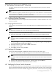
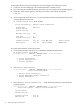
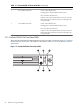
The HP ProLiant DL360 G5 front panel LEDs are shown in Figure 7-1.
Figure 7-1 ProLiant DL360 G5 Front Panel LEDs
4
65
1 2 3 4
Table 7-1 ProLiant DL360 G5 Front Panel LEDs
StatusDescriptionItem
Green = System is on.Power On/Standby button and system
power LED
1
Amber = System is shut down, but power is still applied.
Off = Power cord is not attached, power supply failure has
occurred, no power supplies are installed, facility power is
not available, or disconnected power button cable.
Blue = Identification is activated.Unit Identification Button (UID) button2
Flashing blue = System is being remotely managed.
Off = Identification is deactivated.
Green = System health is normal.Internal health LED3
Amber = System health is degraded. To identify the
component in a degraded state, refer to Section 7.1.4.
Red = System health is critical. To identify the component
in a critical state, refer to Section 7.1.4.
Off = System health is normal (when in standby mode).
Green = Power supply health is normal.External health LED (power supply)4
Amber = Power redundancy failure occurred.
Off = Power supply health is normal when in standby mode.
7.1 HP ProLiant DL360 LEDs 79