
hp StorageWorks NAS e7000 v2 Maintenance and Service Guide
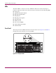

Connectors, LEDs, and Switches
91NAS e7000 v2 Maintenance and Service Guide
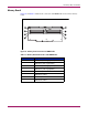
Memory Board
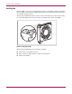
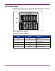
Figure 62 and Table 17 illustrate the connectors and DIMM banks located on the memory
board.
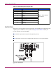
Figure 62: Memory board connectors and DIMM banks
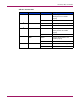
Table 17: Memory Board Connectors and DIMM Banks
Item Description
1
DIMM slot 1, bank A (populated)
2
DIMM slot 2, bank A (populated)
3
DIMM slot 3, bank A (populated)
4
DIMM slot 4, bank A (populated)
5
DIMM slot 5, bank B
6
DIMM slot 6, bank B
7
DIMM slot 7, bank B
8
DIMM slot 8, bank B
1
3
5
7
2
4
6
8
A
B