
Brocade Access Gateway Administrator's Guide (53-1000605-01, October 2007)

Access Gateway Administrator’s Guide 5
53-1000605-01
Port mapping
1
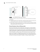
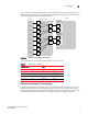
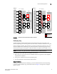
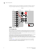
Figure 3 shows a mapping with eight F_Ports evenly mapped to four N_Ports on Brocade Access
Gateway. The N_Ports connect to the same fabric through different edge switches. This example is
also explains mapping, failover, and failback polices.
FIGURE 3 Example F_Port to N_Port mapping
Table 2 describes the mapping and fabric connection shown in Figure 3.
Preferred Secondary N_Port mapping
F_Ports can be mapped to any of the N_Ports on an Access Gateway switch. Each F_Port can be
mapped to only one N_Port as its primary N_Port. When an F_Port is not mapped to any N_Port,
that port is disabled. Optionally, you can specify a Preferred Secondary N_Port for each F_Port. The
Preferred Secondary N_Port, if specified, is used when the primary mapped N_Port fails.
TABLE 2 Example port mapping
Access Gateway Fabric
F_Port N_Port Edge switch F_Port
F_1, F_2 N_1 Switch_A F_A1
F_3, F_4 N_2 Switch_A F_A2
F_5, F_6 N_3 Switch_B F_B1
F_7, F_8 N_4 Switch_B F_B2
N_2
F_A2
Hosts
Access Gateway
Edge Switch
Fabric
(Switch_A)
enabled
NPIV
F_4
F_3
F_2
F_1
N_1
F_A1
enabled
NPIV
N_3
F_B1
enabled
NPIV
Host_1
Host_2
Host_3
Host_4
F_5
Host_5
F_6
Host_6
F_7
Host_7
F_8
Host_8
Edge Switch
(Switch_B)
N_4
F_B2
enabled
NPIV