HP StorageWorks XPath OS 7.4.
Legal and notice information © Copyright 2005 Hewlett-Packard Development Company, L.P. © Copyright 2005 Brocade Communications Systems, Incorporated. Hewlett-Packard Company makes no warranty of any kind with regard to this material, including, but not limited to, the implied warranties of merchantability and fitness for a particular purpose.
Contents About this guide . . . . . . . . . . . . . . . . . . . . . . . . . . . . . . . . . . . . . . . . . . . . . . . . . . . . . . . 7 Intended audience . . . . . . . . . . . . . . . . . . . . . . . . . . . . . . . . . . . . . Related documentation . . . . . . . . . . . . . . . . . . . . . . . . . . . . . . . . . . Document conventions and symbols . . . . . . . . . . . . . . . . . . . . . . . . . Rack stability . . . . . . . . . . . . . . . . . . . . . . . . . . . . . . . . . . . . . . . . .
Matching fabric parameters . . . . . . . . . . . . . . . . . . . . . . . . . . . . . . . . . . . . . . . . . . . . . . . . . . . . . SAN scalability . . . . . . . . . . . . . . . . . . . . . . . . . . . . . . . . . . . . . . . . . . . . . . . . . . . . . . . . . . . . . . Configuring an interfabric link . . . . . . . . . . . . . . . . . . . . . . . . . . . . . . . . . . . . . . . . . . . . . . . . . . . . . . XPath OS and Secure Fabric OS . . . . . . . . . . . . . . . . . . . . . . . . . . . . . . . . . . .
Clearing the system error log . . . Port log . . . . . . . . . . . . . . . . . . . . . Port log management . . . . . . . . . Sample port log. . . . . . . . . . . . . Using the syslog daemon . . . . . . . . . XPath OS syslogd CLI commands . Enabling syslogd . . . . . . . . . . . . Disabling syslogd . . . . . . . . . . . . . . . . . . . .. .. .. .. .. .. .. .. . . . . . . . . .. .. .. .. .. .. .. .. .. .. .. .. .. .. .. .. . . . . . . . . .. .. .. .. .. .. .. .. .. .. .. .. .. .. .. .. . . . . . . .
About this guide This document provides procedures for Storage Area Network (SAN) administrators to set up and manage HP StorageWorks SANs. It is specific to XPath Operating System 7.4.x and the Multi-protocol (MP) Router running XPath OS 7.4.x Intended audience This guide is intended for system administrators and technicians who are experienced with the following: • HP StorageWorks Fibre Channel SAN switches • XPath OS 7.4.
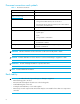
Document conventions and symbols Table 1 Document conventions Convention Element Medium blue text: Figure 1 Cross-reference links and e-mail addresses Medium blue, underlined text (http://www.hp.
HP technical support Telephone numbers for worldwide technical support are listed on the HP support web site: http://www.hp.com/support/. Collect the following information before calling: • Technical support registration number (if applicable) • Product serial numbers • Product model names and numbers • Applicable error messages • Operating system type and revision level • Detailed, specific questions For continuous quality improvement, calls may be recorded or monitored.
1 Introducing XPath OS features XPath OS is the operating system for the HP StorageWorks MP Router. The MP Router is an open, intelligent switching platform for hosting multi-protocol routing services and other applications within a SAN fabric. In addition to the full set of standard Fibre Channel switch features, XPath OS supports optional HP multi-protocol routing services and interoperates with the HP Fabric OS. The MP Router can be used to connect HP fabrics to McDATA fabrics.
FCIP Tunneling Service The FCIP Tunneling Service enables you to extend the Fibre Channel SAN over distances that would be impractical or too expensive with native Fibre Channel links. The service employs a proprietary transport protocol that allows the transparent interconnection of geographically distributed SANs through an IP-based network. XPath OS supports FCIP between two MP Routers only, not between an MP Router and another switch model.
F ibre C hannel initiator F ibre C hannel target IP network EX_Port VE_Port VE_Port EX_Port F abric 1 F abric 2 Multiprotoc ol R outer Multiprotoc ol R outer Figure 2 Combining FCIP tunneling and FC-FC routing services Fibre Channel features XPath OS provides the Fibre Channel features described in Table 2. Table 2 XPath OS Fibre Channel switch features Feature Description Arbitrated-loop support The MP Router supports only one arbitrated-loop physical address (AL_PA) device per port.
Table 2 XPath OS Fibre Channel switch features (continued) Feature Description Point-to-point and loop mode topologies MP Router ports can be configured to support either point-to-point mode or loop mode using the portCfgTopology command.
PID mode requirements Either core port identifier (PID) mode or extended-edge PID mode must be enabled to successfully execute the XPath OS. In its default configuration, XPath OS has core PID mode enabled. All switches within a fabric must have the same PID mode enabled. For more information on configuring a fabric PID mode, see ”Verifying the PID mode” on page 20. For information on configuring the PID mode in Fabric OS, see the HP StorageWorks Fabric OS 5.x administrator guide.
Table 3 16 Monitored XPath OS daemons Daemon Description Failure Default Chassismgr Chassis manager: Captures all the management functionalities that apply only at the switch level, for example psShow, fanShow, ipAaddrSet, and chassisShow. Base Reboot Chassispd Chassis performance daemon: Periodically monitors certain chassis elements and stores the information in shared memory.
Table 3 Monitored XPath OS daemons (continued) Daemon Description Failure Default Snmpd Simple Network Management Protocol daemon: MANAGEABILITY daemon for monitoring and managing a network device/switch. Base Restart Xmld XML-rpc daemon: Handles communication with Web Tools GUI client using xml-rpc. Base Restart Zsd Zoning daemon: Provides the services of Fibre channel zoning for use with Fabric Zone Merge and zoning configurations. Base Reboot High availability XPath OS 7.4.
Introducing XPath OS features
2 Performing basic configuration This chapter provides procedures for the basic switch configuration tasks that are frequently performed as part of routine SAN administration: • Viewing router information, next • Verifying the PID mode, page 20 • Creating interswitch links, page 21 • Configuring a long-distance connection, page 22 • Verifying connectivity, page 23 • Synchronizing time with an NTP server, page 23 • Licensed features, page 24 • Changing account passwords, page 24 • Enabling and disabling swi
For example: router:admin> switchshow Switch Name : FabricAP Switch State : Online Switch Type : 38.
1. Issue the switchDisable command to disable the switch. 2. Issue the configure command. 3. Press Enter after the prompts until the Switch PID Address Mode prompt appears. 4. At the Switch PID Address Mode prompt, enter 1 to enable core PID mode, or enter 2 to enable extended-edge PID mode. 5. Issue the switchEnable command to enable the switch. Creating interswitch links When you physically connect cables from an MP Router to other MP Routers or to Fabric OS-based switches, a fabric forms automatically.
Disabling the Management Server feature (Fabric OS or Secure Fabric OS switch only) 1. Issue the secModeShow command to see whether the Secure Fabric OS feature is enabled: • If it is disabled, go directly to step 3. • If it is enabled, log in to the primary FCS switch with secure telnet (sectelnet) or secure shell (SSH), and continue with step 2. For details on sectelnet and SSH, see the HP StorageWorks Secure Fabric OS user guide. 2.
Table 4 ISL modes (continued) Mode Description Maximum ISL distance LE Level E 10 km at 1 Gbit/sec or 2 Gbit/sec LS Level S 300 km at 1 Gbit/sec or 2 Gbit/sec Configuring port 15 for the LS distance level : router:admin> portdisable 15 Port 15 disabled. router:admin> portcfglongdistance 15 LS Distance level is set to LS on port 15. router:admin> portenable 15 Port 15 enabled. Verifying connectivity Verify fabric-wide device connectivity by displaying the fabric-wide device count.
Using an NTP server for time service 1. Log in as admin. 2. Issue the following command: tsclockserver “[ipaddr]” The optional ipaddr parameter is the IP address of the NTP server, which must be accessible from the MP Router. The default value is LOCL (local). For example: router:admin> tsclockserver LOCL router:admin> tsclockserver “132.163.135.131” router:admin> tsclockserver 132.163.135.
Without name specified, you are prompted to change the password for the current account. You must enter the old password and the new password and then re-enter the new password. The maximum length of a password is eight characters. If name is specified and the current account has the admin role, the specified account password is reset to the default value.
Enabling a port 1. Log in as admin. 2. Issue the portEnable command: router:admin> portenable 1 port 1 enabled Disabling a port 1. Log in as admin. 2. Issue the portDisable command: router:admin> portdisable 1 port 1 disabled If the port is connected to another switch, the fabric might reconfigure. If the port is connected to one or more devices, the devices are no longer available to the fabric.
5. Issue the portstart command to start the ports. For example: portstart 8-15 6. Issue the portenable command to enable the ports. For example: portenable 8-15 7. Option: Issue the portshow command to verify that the newly active ports are Started. NOTE: If you remove the HP StorageWorks MP Router Upgrade License, ports 8 through 15 no longer work after the next reboot. Setting the domain ID A domain ID is assigned dynamically when a switch is enabled.
For example: router:admin> switchdisable Switch is being disabled.. .............. router:admin> configure Fabric parameter set. to skip a parameter Domain: (1..239 or f(fabric_assign)) [100 unconfigured] 5 BB Credit: [1..32] [16] R_A_TOV: (4000..120000) [10000] E_D_TOV: (1000..5000) [2000] Data field size: (256..2112 multiple of 4) [2112] Switch PID Address Mode (1..2) [1] WAN_TOV (0..R_A_TOV/4 ) [0] MAX_HOP_COUNT (7..19 ) [7] End-device RSCN Transmission Mode (0..
DLS is enabled by default. When DLS is enabled, routing changes can affect working ports. For example, if an Fx_Port goes down, another Fx_Port might be rerouted from one E_Port to a different E_Port. The switch minimizes the number of routing changes, but some are necessary to achieve optimal load sharing. If DLS is disabled (using the dlsReset command), load-sharing route determination is performed only at boot time or when an Fx_Port comes up. Optimal load sharing is rarely achieved with DLS disabled.
2. Issue the topologyShow command: router:admin> topologyshow 8 domains in the fabric; Local Domain ID: 100 Domain Metric Hops Out Port Name ----------------------------------------------------1 500 1 9 "switch154" 2 1250 2 5 "switch101" 8 3 500 1 5 "switch252" 8 4 1250 2 5 "switch165" 8 25 1250 2 5 "msit_ref_term" 8 210 2750 4 5 "switch210" 8 211 2250 3 5 "switch211" 8 router:admin> The following information is displayed: • Domain: The destination domain of incoming frame.
• Next (Dom, Port): Domain and port number of the next hop. These are the domain number and the port number of the switch to which Out-Port is connected. Displaying command help XPath OS provides a help page for each command, explaining what the command does, its syntax, any operands, and the account role required to run the command. Displaying help information about a command 1. Log in as admin. 2.
Performing basic configuration
3 Performing basic maintenance This chapter provides procedures for installing software, maintaining configuration files, and checking hardware status. This information is provided in the following sections: • Maintaining the router configuration, next • Maintaining firmware, page 35 • Performing hardware checks, page 41 Maintaining the router configuration It is important that fabric configuration settings be consistent across the fabric, because inconsistent parameters can cause fabric segmentation.
3. Issue the configUpload command: configupload -h hostName -f destFileName -u userName -p password [-t fileTransferProtocol] [-l configuration] where: -h hostName Specifies the IP address of the FTP server. -f destFileName Specifies the destination file name. -u userName Specifies the account name on the FTP server. -p password Specifies the password for the account. -t fileTransferProtocol Specifies the file transfer protocol. -l configuration Displays the current upload configuration.
NOTE: Depending on your site security procedures, you might want to keep a record of the accounts and passwords for all switches in the fabric. Because this is sensitive information, you should limit access to it. Maintaining firmware For the latest Multi-protocol Router firmware updates, visit the MP Router web site: http://h18006.www1.hp.com/products/storageworks/mprouter/index.html.
Displaying the installed version Issue the version command to display information about the firmware version that is currently installed: router:admin> version =================== Installed Packages: =================== Package Name: xpath_os_v7.4.0_bld17 Install Date: Apr 14, 2005 18:48 router:admin> Installing a package CAUTION: Whenever you install a base version of the firmware, any previously installed add-on packages, such as third-party applications, need to be reinstalled.
To upgrade from XPath 7.4.x to 7.4.y Two kinds of software updates are supported for XPath 7.4.0. These include updating the XPath base only and updating the recovery kernel and the base at the same time. These methods both use the firmwaredownload command, similar to the upgrade procedure from XPath OS 7.3.x to 7.4.0. Use the following procedure: 1. Log in to the MP Router as admin. 2. Use the firmwaredownload command to install the package from the host to the MP Router.
# version RPG file server : 192.168.194.26 Root directory : /dump/74_73_downgrade FTP username : root FTP password : ****** Download protocol : ftp ================== Installed Packages: =================== Package Name : xpath_os_v7.3.0c Installed from : bank1 Installed date : Sep 8 15:39 Administrative status : (1) Primary status : up Secondary status : installed and running Disk usage on root fs - Total: 198 Mbytes, Free: 99 Mbytes. 3.
Downgrading from XPath OS 7.3.0 or later to a previous version This section describes how to downgrade to an earlier release of XPath OS. If the MP Router is running XPath OS 7.3.0 or later and you want to downgrade to release 7.2.x or earlier, follow these steps. Before you begin, make sure that you have the following required items|: • Access to the platform through its serial port, using a serial cable and a terminal emulator. • The correct recovery kernel version: • 1.4.1.3 for XPath OS 7.3.x • 1.3.0.
The following example shows a recovery to XPath OS 7.1.x using the recovery kernel version 1.3.0.0. Multiprotocol Multiprotocol Multiprotocol Multiprotocol Multiprotocol Multiprotocol Multiprotocol Router> Router> Router> Router> Router> Router> Router> set currentdnldproto tftp set bootserver ipaddr-of-the-tftp-server set basefile XPathRecoverAP7420 set cfgbank bank0 set rootdir / set bank0ver 1.3.0.
Performing hardware checks You can view hardware status and modify the power supply status threshold. Viewing hardware status Three components determine the overall status of the hardware: • Fan speed • Power supply • Temperature If the status of any component is marginal, overall status is Marginal. Likewise, if the status of any of the components is down, the overall status is Down. In all other cases, overall status is Healthy. Individual rules determine the status of each component.
This command displays operational status and traffic statistics, for example: router:admin> portshow 12 port 12 info Configuration Current Name : port 12 State: STARTED UP Type : FC FC Link Status: ENABLED UP Topology: P-P P-P Speed: AN N2 LinkCost: AUTO 500 Distance: L0.5(LM) L0.5(LM) WWN: 20:0c:00:05:1e:12:f8:00 Licensed : YES Diag result : PASSED inFrames: outFrames: inOctets: outOctets: discards: 188 188 11408 8368 0 Viewing fan status 1. Log in as admin. 2.
Viewing temperature status Use the tempShow command to display readings of all temperature sensors in the MP Router: 1. Log in as admin. 2. Issue the tempShow command: router:admin> tempshow Index Status Centigrade Fahrenheit ---------------------------------------------------1 OK 21 70 2 OK 22 72 3 OK 29 84 4 OK 24 75 5 OK 25 77 The possible values for temperature status are: • OK: Temperature is within the acceptable range. • MARGINAL: Temperature is outside the acceptable range.
Performing basic maintenance
4 Using the FC-FC Routing Service The FC-FC Routing Service is an optional, fee-based license that provides Fibre Channel routing between two or more fabrics without merging those fabrics. The MP Router can be used simultaneously as a Fibre Channel router and as an FCIP tunnel.
Edge Fabric 2 Edge Fabric 1 = LSAN Multiprotocol Router 10 Edge Fabric 3 Figure 3 Simple meta-SAN Figure 4 shows a meta-SAN consisting of two edge fabrics connected through an MP Router with interfabric links.
Backbone Fabric Multiprotocol Router Multiprotocol Router Edge SAN 1 Edge SAN 2 11 = LSAN Figure 5 Edge SANs connected through a backbone fabric Proxy devices In an isolated SAN, the physical topology of the interconnections between nodes and switches is closely modeled by the logical topology of the connections between PIDs; this is not so in a meta-SAN. With an MP Router in a meta-SAN, a node is projected into the logical topology as a proxy device. This is a proxy topology.
Host Proxy Host Proxy Target Target Multiprotocol Router 13 Fabric 2 Fabric 1 Figure 6 Proxy topology LSANs and zoning An LSAN is defined by a zone in an edge fabric. You can define and manage LSANs using HP Advanced Zoning or HP Fabric Manager. Zones are locally defined. Names and memberships, with the exception of hosts and targets exported from one fabric to another, do not need to be coordinated between the edge fabrics.
1. Connect to switch1, log in as admin, and create and enable the first LSAN zone: a. Use the nsShow command to list the WWN of the host (10:00:00:00:c9:2b:6a:2c). b. Use the zoneCreate command to create the LSAN zone called lsan_zone_fabric1, which includes the host. c. Use the zoneAdd command to add Target A to the LSAN zone. d. Use the cfgCreate and cfgEnable commands to create and enable the LSAN zone configuration.
On the MP Router, the host and Target A are imported, because both are defined by lsan_zone_fabric1 and lsan_zone_fabric2. However, Target B, which is defined by lsan_zone_fabric2, is not imported because lsan_zone_fabric1 does not allow Target B to be imported.
Proxy devices are presented to the fabric as being topologically attached to phantom domains created by the FC-FC Routing Service. The MP Router creates two types of phantom domains for each edge fabric accessed: • Each EX_Port projects a unique front phantom domain (front domain). • Each EX_Port also projects one translate phantom domain (xlate domain) for each edge fabric accessed through it.
For example, suppose the maximum number of Name Server entries is 1024. Consider Fabric A with 700 devices and Fabric B with 600 devices. If you try to merge Fabrics A and B, the result requires 1300 Name Server entries, which exceeds the maximum of 1024. Using Fibre Channel routing, you can perform either of the following: • Import up to 324 hosts or targets to Fabric A from Fabric B (700 + 324 = 1024) • Import up to 424 hosts to Fabric B from Fabric A (600 + 424 = 1024).
The PID mode for the MP Router (the backbone fabric PID mode) and the edge fabric PID mode do not need to match, but the PID mode for the EX_port and the edge fabric to which it is attached must match. The various edge fabrics may have different PID modes. 6. Configure each port that connects to a backbone fabric as an E_Port. 7. Assign the backbone fabric ID: a. Issue the switchDisable command to disable the switch. b. Issue the fcrConfigure command.
XPath OS and Secure Fabric OS Beginning with XPath OS 7.4.x, the MP Router supports routing between secure fabric employing HP Secure Fabric OS with non-secured fabrics through Challenge-Handshake Authentication Protocol (DH-CHAP). Secure Fabric OS is an optional, licensed product that provides customizable security restrictions through local and remote management channels on an HP StorageWorks fabric.
When you have the necessary information, configure the secret words on the MP Router. 1. Log in to the MP Router with administrative privileges. 2. Issue the secAuthSecret command: secAuthSecret --set The secret must consist of 8 to 40 characters. Setting up secret keys does not initiate DH-CHAP authentication. DH-CHAP authentication is performed whenever a port or a switch is enabled. 3. Follow the instructions provided on screen, as shown in the following example: a. Enter the port or switch WWN. b.
Configuring a DH-CHAP secret on the Fabric OS switch You must know the front domain WWN of the MP Router to use as the peer entry when setting the secret word on the Fabric OS switch.
The DH-CHAP secret is now stored in the secret word database and is ready for use. For example: router:admin> secAuthSecret --set This command sets up secret keys for the DH-CHAP authentication. The minimum length of a secret key is 8 characters and maximum 40 characters. Setting up secret keys does not initiate DH-CHAP authentication. It is performed whenever a port or a switch is enabled. Following inputs should be specified for each entry. 1. WWN for which secret is being set up. 2.
Monitoring resources It is possible to exhaust resources, such as proxy PIDs. Whenever a resource is exhausted, the MP Router generates an error message. Messages are described in the HP StorageWorks XPath OS 7.4.x system error messages reference guide.
There are some devices that do not support the ELS ECHO request. In these cases, the device either does not respond to the request or sends an ELS reject. When a device does not respond to the ELS request, further debugging is required; however, do not assume that the device is not connected to the Fibre Channel. For details about the fcPing command, see the HP StorageWorks Fabric OS command reference guide. Connecting to McDATA SANs XPath OS 7.4.
Table 6 portCfgExPort -m interop parameters Value Description 0 HP Native (default) 1 McDATA Open mode See the HP StorageWorks XPath OS 7.4.x command reference guide for details about the portCfgExPort command and other XPath OS commands. Once the port is properly configured and connected, log in to the MP Router and issue the switchShow command. For example: router:admin> switchshow Switch Name : routerA Switch State : Online Switch Type : 38.
Configuring the fabrics for interconnectivity When connecting an HP fabric with a McDATA fabric using the MP Router, you must configure the switch on both fabrics as well as the MP Router.
The following example sets port 14 to admin-enabled, assigns a Fabric ID of 10, and sets the port to Core PID. For complete information about any XPath OS command, see the HP StorageWorks XPath OS 7.4.x command reference guide. switch:admin> portcfgexport 14 -a 1 -f 10 -p 1 4. Restart the port by issuing the portStart command. 5. Still on the MP Router, use the portStop command to stop the EX_Port that is to be used to connect to the McDATA switch. router:admin> portstop 1 port 1 stopped. router:admin> 6.
Figure 7 SAN Pilot Preparing the HP StorageWorks switch for connectivity Now that the MP Router is configured to connect to a McDATA fabric, you must create your LSAN and zones for the SAN. Either of the following procedures may be used. 1. Create a telnet connection to the HP StorageWorks switch. You can also use Advanced Web Tools to perform this procedure. 2. Configure the LSAN, using the LSAN_xxxx naming schema.
6. Issue the cfgEnable command to enable the zone configuration.: switch:admin> cfgenable "Domain1" zone config "Domain1" is in effect Updating flash ... 7. Optional: Reissue the cfgShow command to verify that the zoning is correct.
SAN Pilot EFCM Figure 8 SAN Pilot and EFCM zones 4. Enter the desired name in the Zone Name box using the LSAN_xxxx naming schema. • In EFCM, move to the list of ports and nodes, and highlight the devices to include in the LSAN. • In SAN Pilot, click Add New Zone and then select the new zone to display the Modify Zone tab (see Figure 9). Add the desired devices to the zone. Figure 9 Modify Zone tab 5.
Figure 10 World Wide Name box If you are using EFCM, use Add Detached Node to enter the WWN port name (see Figure 11). Figure 11 Modify zone window 6. Move to the Zone Set tab in SAN Pilot. If you are using EFCM, or the Zoneset Library window, tab to Zone Sets and select File > New.
7. Enter a name for the zoneset in the Zone Set Name box. 8. Select the zone to include in this zoneset and click Add Zone Set. The steps for EFCM are similar. 9. In SAN Pilot, click Save and Activate Zoning Configuration. In EFCM, return to the main window and select Configure, and then select Activate Zone Set to launch the zoneset activation window (Figure 12). Figure 12 Activate zone set 10.Highlight the zoneset to be activated and then click Next. 11.
5. Move back to the MP Router and issue the fcrProxyDevShow command to verify that the devices are configured and exported.
7. Log in to the HP StorageWorks switch and issue the nsAllShow command. All the devices from both LSANs should appear in the output. If they do not, issue the cfgShow command to verify your zone configuration. XPath OS 7.4.
Using the FC-FC Routing Service
5 Using the FCIP Tunneling Service The optional FCIP Tunneling Service enables Fibre Channel frames to tunnel through IP networks by dividing frames, encapsulating the result in IP packets upon entering the tunnel, and then reconstructing them as they leave the tunnel.
Configuring an FCIP interswitch link You must configure both the local and the remote MP Routers to enable an FCIP ISL. This configuration requires the use of the portCfgFcip command (not the portCfgExPort command). If the two MP Routers have a direct connection between them (no router in between), the IP addresses for both routers must be in the same subnet, and the default gateway setting is not required.
The example sets the port type to GigE, sets the GigE port parameters, and configures and enables the FCIP ISL. See the portType command in the HP StorageWorks XPath OS 7.4.0 command reference guide for additional information on configuring GigE ports and the portCfgGige command for additional information on configuring GigE parameters for the ports. A given port can be configured for only one FCIP ISL. Configuring the local MP Router 1. Stop the port: router:admin> portstop 1 port 1 stopped. 2.
3. Set the GigE port parameters. The following example is for local and remote ports on the same subnet: router:admin> portcfggige 4 -i 10.2.3.23 -n 255.255.255.0 -v 1 -p fcip port 4 proto set to: fcip port 4 proto ver set to: 1 port 4 ipaddress set to: 10.2.3.23 port 4 net mask set to: 255.255.255.0 If the local and remote ports are on different subnets, use the -g option to specify the gateway: router:admin> portcfggige 4 -i 10.2.4.23 -n 255.255.255.0 -g 10.2.4.1 -v 1 -p fcip 4.
router:admin> rnping 1 10.2.3.23 -l 1200 Pinging 10.2.3.23 Reply from 10.2.3.23: bytes=1200 time<14ms TTL=255 Reply from 10.2.3.23: bytes=1200 time<14ms TTL=255 Reply from 10.2.3.23: bytes=1200 time<14ms TTL=255 Reply from 10.2.3.23: bytes=1200 time<14ms TTL=255 Reply from 10.2.3.23: bytes=1200 time<14ms TTL=255 The rnping is completed router:admin> portshow 1 port 1 info Configuration Current Name : port_1 State: STARTED UP Type : GIGE GIGE Link Status: ENABLED UP IP addr: 10.2.3.23 10.2.3.
Disabling and enabling an FCIP interswitch link You can disable a configured FCIP ISL by changing the admin state to disabled on both the local and the remote MP Router, using the following syntax: portcfgfcip portnumber -a 2 You can re-enable a disabled FCIP ISL by changing the admin state to enabled on both the local and remote MP Router, using the following syntax: portcfgfcip portnumber -a 1 76 Using the FCIP Tunneling Service
6 Using the iSCSI Gateway Service The HP iSCSI Gateway Service facilitates communication between TCP/IP networks and Fibre Channel SANs. It displays iSCSI gateway configuration information across multiple MP Routers.
If there are multiple iSCSI portals on one MP Router, configuration information, such as IQN-to-WWN mapping and CHAP secrets, is automatically shared among the portals. If there are iSCSI portals on more than one MP Router, you can use the IP fabric configuration server (iFCS) to control the sharing of iSCSI gateway configuration information across multiple MP Routers. Summary of configuration steps The configuration of an iSCSI gateway is illustrated in Figure 16.
5. Issue the portShow command to verify the configuration. For example: router:admin> portstop 1 port 1 stopped. router:admin> porttype 1 g port 1 set to type GIGE router:admin> portcfggige 1 -i 192.168.0.10 -n 255.255.255.0 -g 192.168.0.1 -p iscsi port 1 proto set to: iscsi port 1 proto ver set to: 1 router:admin> portstart 1 port 1 started router:admin> portshow 1 port 1 info Configuration Current Name : port_1 State: STARTED UP Type : GIGE GIGE Link Status: ENABLED UP IP addr: 192.168.0.10 192.168.0.
Configuring CHAP The iSCSI standard supports access control with CHAP. You can configure the iSCSI gateway to use one-way authentication, where the target authenticates the initiator, or two-way authentication, where first the target authenticates the initiator and then the initiator authenticates the target. NOTE: The MP Router supports DH-CHAP only. It consists of the CHAP protocol combined with the Diffie-Hellman exchange.
A secondary switch automatically becomes the primary if the current primary is removed from the fabric. When this occurs, the primary selection is based on the second and third least-significant bytes of the switch WWN. The secondary switch in the fabric with the larger value of those two bytes becomes the primary. For example, a secondary with a WWN of 10:00:00:05:1e:15:84:00 becomes primary over another secondary with a WWN of 10:00:00:05:1e:12:de:00 because 0x1584 is larger than 0x12de.
Working with the WWN mapping table The WWN is an HP Organizational Unique Identifier (OUI). You can use the iscsiWwnAlloc command to assign WWNs. Displaying the WWN list Issue the iscsiWwnAlloc command with no arguments. You can use the aliShow, zoneShow, and cfgShow commands with the -i option to display IQNs.
Fibre Channel target iSCSI initiator Configure iSCSI IP network IP1 iSCSI Gateway 1 IP2 IP3 iSCSI Gateway 2 Fibre Channel SAN Figure 17 iSCSI high availability configuration Enabling failover 1. Issue the ifcsEnable command to enable iFCS. 2.
Using the iSCSI Gateway Service
7 Creating and maintaining zones This chapter provides procedures for using XPath OS zoning in the following sections: • Zoning terminology, page 86 • Zoning enforcement, page 86 • Configuring zones, page 87 You can use zones to create logical subsets of the fabric to accommodate environments such as closed user groups or functional areas within the fabric. Any zone object connected to the fabric can be included in one or more zones. Zone objects can communicate only with other objects in the same zone.
Zoning terminology A zone is a specified group of fabric-connected devices, also called zone objects. Any device or zone object connected to the fabric can be included in one or more zones. Zone objects within a zone can communicate only with other zone objects in the same zone. After zoning is enabled, if a device is not explicitly defined in a zone, that device is isolated and is inaccessible to other devices in the fabric.
The MP Router zone server implementation complies with Fabric OS 2.6.x, 3.x, and 4.x. In multiswitch configurations, the MP Router also complies with the FC-SW2 zone server specification. The maximum number of members allowed in the zone server depends on the size of the zone database; the effective zone database can have a maximum of 4096 zone members and 1024 zones (including fabric assisted zones). The maximum zoning database size is 128 KB.
5. Check that the zone configuration is correct: router:admin> zoneshow Defined configurations: Cfg: backupcfg zone1;zone2 Zone: zone1 host1 Zone: zone2 1,7 Alias: host1 1,6 Effective configuration: No configuration enabled 6. Enable the zone configuration: router:admin> cfgenable “backupcfg” Cfg Enable Successful 7. Save the zone configuration: router:admin> cfgsave Cfg save Successful 8.
Implementing an iSCSI name in zoning 1. Create an alias: router:admin> alicreate “ALIAS_2”, “iqn.2001-04.com.example:arraysa86” Alias Create Successful 2. Create a zone: router:admin> zonecreate “ZONE_C”, “iqn.2002-04.com.example:arraysa86” Zone Create Successful 3. Check the zone configuration: router:admin> cfgshow -i Defined configurations: Cfg: cfg_iscsi ZONE_C zone: ZONE_C iqn.2002-04.com.example:arraysa86 alias: ALIAS_2 iqn.2001-04.com.
Table 9 Zoning commands (continued) Command Description cfgAdd Adds a zone to a zone configuration cfgActvShow Prints the effective zone configuration cfgClear Clears all zone configurations cfgCreate Creates a zone configuration cfgDelete Deletes a zone configuration cfgDisable Disables a zone configuration cfgEnable Enables a zone configuration cfgRemove Removes a zone from a zone configuration cfgSave Saves zone configurations in flash memory cfgShow Displays zone configurations in
8 Using ISL trunking This chapter provides information on HP Interswitch Link (ISL) trunking, and consists of the following sections: • How exchange-based trunking works, next • Enabling trunking, page 92 • Managing trunking, page 92 • Trunking commands, page 93 How exchange-based trunking works The MP Router exchange-based trunking feature increases overall bandwidth by distributing network traffic across ISLs connecting pairs of switches.
data-frame-by-data-frame level, load is instead rebalanced each time an initiator or target device's connection or disconnection impacts the routing behavior of a given ISL path. All ingress ports share all available routes to a destination domain. There is a maximum of 16 routes to a destination domain. In the fabric illustrated in Figure 19, Domain 100 egress ports 1, 2, 3, and 4 can be used to reach destination Domain 200.
Determining whether the trunking feature is enabled on your switch 1. Log in as admin. 2. Issue the trunkShow command: router:admin> trunkshow Trunking is disabled Enabling trunking on a switch 1. Log in as admin. 2. Issue the trunkSet command: router:admin> trunkset Trunk feature enabled All Fibre Channel ports that passed POST are enabled for trunking. If the switch was part of a fabric, the fabric reconfigures. Disabling trunking on a switch 1. Log in as admin. 2.
Table 10 94 Trunking commands (continued) Command Description topologyShow Displays the fabric topology, as seen by the local switch trunkReset Disables trunking on a switch trunkSet Enables trunking on a switch trunkShow Displays whether trunking is enabled or disabled on the switch urouteShow Displays the unicast routing information for a port Using ISL trunking
9 Monitoring system logs This chapter discusses the following topics: • System error log, next • Port log, page 97 • Using the syslog daemon, page 98 There are three log file systems in the XPath OS: • The system error log displays system daemon errors, in addition to all events from the event log. • The port log displays port information. • The event log displays events only. Log entries for all three logs are described in the HP StorageWorks XPath OS 7.4.x system error messages reference guide.
Table 12 Message severity levels Event level Description 0 = Panic Panic messages indicate that a specific software subsystem has detected a fatal or unrecoverable error condition. Examples are memory allocation failure, system call failure, and software detection of problems with the ASIC or with hardware subsystems. These errors usually indicate partial or complete failure of a subsystem.
Table 13 System error log message field descriptions Example Variable name Description Error 239 Error log buffer number Displays a rotating number that describes the position the message holds in the buffer. This number is not permanently associated with the error itself and should not be used when contacting your service provider; provide the error code name instead. 301 (EvtMgr) Reporting process ID Displays the process ID and name of the module reporting the error.
Table 14 Port log management commands Command Description portLogClear Clears port logs for all or specified ports portLogDisable Disables port logs for all or specified ports portLogDump Displays port logs for all or specified ports, without page breaks portLogEnable Enables port logs for all or specified ports portLogShow Displays port logs for all or specified ports, with page breaks See the HP StorageWorks XPath OS 7.4.x command reference guide for detailed information on these commands.
Table 15 syslogd configuration commands Command Purpose syslogdIpAdd Adds the IP address of the remote syslogd host to the MP Router syslogdIpRemove Removes the IP address of the remote syslogd host from the MP Router syslogdIpShow Shows the list of configured syslogd IP addresses on the MP Router eventShow Displays messages from the event log on the MP Router errShow Displays messages from the system error log on the MP Router errClear Clears messages from the system error log on the MP Rout
Monitoring system logs
A Hard zoning background In XPath OS hard zoning, the frame source and destination addresses are compared to permitted addresses at the MP Router ingress F_Port or FL_Port (for devices directly attached to the MP Router) or at the egress F_Port or FL_Port (for devices directly attached to a non-HP switch). You do not need to know the details of hard zoning to configure zones or for routine administration of the MP Router. Each MP Router maintains a zone server.
If the destination ID is directly attached to an MP Router port (as in Figure 22), the S_ID/D_ID pair is checked against the list of allowed combinations and is dropped if the pair is not permitted. Port M Port N Target Host Fibre Channel switch Multiprotocol Router Figure 22 Host and target in a heterogeneous fabric, combination 1 If the destination ID is not directly attached to an MP Router port (as in Figure 23), the combination is not checked.
B Recovery kernel for XPath OS 7.4.x The recovery kernel (RK) is a part of the XPath OS that is stored in a reserved portion of memory, protected from erasure. This kernel provides the mechanics of the boot process: It allows the hardware to locate and boot the proper bank. The kernel finds either bank1 or bank2 as bootable. This bank can then be used to recover firmware. The NVRAM value, cfgBank, dictates the bank from which to boot. When entering NRAM values, use lowercase only.
Installing the XPath OS 7.4.0 base firmware from the recovery kernel 1. Clear the storage of old files by entering: format all at the recovery kernel prompt and then pressing Enter at the recovery kernel prompt. 2. After you are returned to a prompt, issue the firmwareDownload command with the necessary parameters. In the following example, the boot server is located at the IP address 192.168.25.100, the FTP-access user name is user, and the file xpath_os_v7.4.0 is stored in the /tftpboot directory.
Glossary AL_PA Arbitrated-loop physical address. A unique 8-bit value assigned during loop initialization to a port in an arbitrated loop. Also called arbitrated-loop parameters. alias A logical grouping of elements in a fabric. An alias is a collection of port numbers and connected devices used to simplify the entry of port numbers and WWNs when creating zones. alias server A fabric software facility that supports multicast group management.
core PID Core switch port identifier. The core PID must be set for Fabric OS 3.1 and earlier switches included in a fabric of Fabric OS 4.1 switches. This parameter is located in the configure command of Fabric OS 3.1 and earlier. All Fabric OS 4.1 switches and later use the core PID format by default; this parameter is not present in the configure command for these switches. credit In Fibre Channel technology, the number of receive buffers available to transmit frames between ports.
exported device A device that has been mapped between fabrics (a host or storage port in one edge fabric can be exported to any other fabric by using LSAN zoning). F_Port Fabric port. A port that is able to transmit under fabric protocol and interface over links. It can be used to connect an N_Port to a switch. See also FL_Port, Fx_Port, N_Port. fabric A collection of Fibre Channel switches and devices, such as hosts and storage. Also called a switched fabric. See also SAN, topology.
FC-GS-2 Fibre Channel generic services, second generation. FC-GS-3 Fibre Channel generic services, third generation. FC_IP Fibre Channel over IP. FC-NAT Fibre Channel network address translation. FC-PH The Fibre Channel physical and signaling standard for FC-0, FC-1, and FC-2 layers of the Fibre Channel Protocol. Indicates signaling used for cable plants, media types, and transmission speeds. FC-PH-2 Fibre Channel Physical Interface, second generation.
FC-SW-2 The second-generation Fibre Channel Switch Fabric standard defined by ANSI. Specifies tools and algorithms for the interconnection and initialization of Fibre Channel switches to create a multiswitch Fibre Channel fabric. Fibre Channel The primary protocol used for building SANs to transmit data between servers, switches, and storage devices. Unlike IP and Ethernet, Fibre Channel was designed to support the needs of storage devices of all types.
FTS Fiber Transport Services. Fx_Port A fabric port that can operate as either an F_Port or FL_Port. See also F_Port, FL_Port. G_Port Generic port. A port that can operate as either an E_Port or an F_Port. A port is defined as a G_Port when it is not yet connected or has not yet assumed a specific function in the fabric. See also F_Port, FL_Port. gateway Hardware that connects incompatible networks by providing translation for both hardware and software.
ISL Interswitch link. A Fibre Channel link from the E_Port of one switch to the E_Port of another. See also E_Port. JBOD Just a bunch of disks. A number of disks connected in a single chassis to one or more controllers. See also RAID. L_Port Loop port. A node port (NL_Port) or fabric port (FL_Port) that has arbitrated-loop capabilities. An L_Port can be in either Fabric Mode or Loop Mode. LAN Local area network. A network in which transmissions typically take place over fewer than 5 kilometers (3.4 miles).
MS Management Server. Allows a SAN management application to retrieve information and administer the fabric and interconnected elements, such as switches, servers, and storage devices. The MS is located at the Fibre Channel well-known address FFFFFAh. MSD Management Server daemon. Monitors the MS. Includes the Fabric Configuration Service and the Unzoned Name Server. MSRS Multi-protocol SAN Routing Services.
originator The Nx_Port that originated an exchange. out-of-band Transmission of management protocol outside of the Fibre Channel network, usually over Ethernet. OX_ID Originator ID or exchange ID. Refers to the exchange ID assigned by the originator port. packet A set of information transmitted across a network. See also frame. parallel The simultaneous transmission of data bits over multiple lines. path selection The selection of a transmission path through the fabric.
port log dump A view of what happens on a switch, from the switch's point of view. The portlogdump command is used to read the port log. port name A user-defined alphanumeric name for a port. port_name The unique identifier assigned to a Fibre Channel port and communicated during login and port discovery. POST Power-on self-test. A series of tests run by a switch after it is turned on. protocol A defined method and set of standards for communication.
SAN port count The number of ports available for connection by nodes in the entire SAN. scalability One of the properties of a SAN; the size to which a SAN topology can grow port and switch counts with ease. SCN State change notification. Used for internal state change notifications, not external changes. This is the switch logging that the port is online or is an Fx_Port, not what is sent from the switch to the Nx_Ports. SCR State change registration.
switch port A port on a switch. Switch ports can be E_Ports, F_Ports, or FL_Ports. syslogd Syslog daemon. Used to forward error messages. target A storage device on a Fibre Channel network. See also initiator. TCP/IP Transmission Control Protocol Internet Protocol. A communications protocol developed under contract from the U.S. Department of Defense to internetwork dissimilar systems. telnet A virtual terminal emulation used with TCP/IP. Telnet is sometimes used as a synonym for the HP Fabric OS CLI.
U_Port Universal port. A switch port that can operate as a G_Port, E_Port, F_Port, or FL_Port. A port is defined as a U_Port when it is not connected or has not yet assumed a specific function in the fabric. WAN_TOV Wide area network timeout value. well-known address In Fibre Channel technology, a logical address defined by Fibre Channel standards as assigned to a specific function and stored on the switch. WWN World wide name. An identifier that is unique worldwide.
Index A account passwords, changing 24 activating licenses 92 Ports on Demand 26 administering iSCSI configurations 80 aliAdd command 88 aliCreate command 88 aliRemove command 88 aliShow command 82, 88 allocating frame buffers 22 altBoot command 35 arbitrated-loop device support 13 archive files, maximum number of 95 assigning domain IDs 27 audience defined 7 authorized reseller, HP 9 B backbone fabric ID 53 benefits, interconnectivity 59 C cfgCreate command 49, 63 cfgEnable command 49, 64 cfgShow command
switchDisable 21, 25, 27, 34, 53 switchEnable 21, 25, 27, 53 switchShow 23, 54, 60, 68 switchStatusShow 41 syslogdIpAdd 99 syslogdIpRemove 99 tempShow 43 topologyShow 30, 93 trunking 93 trunkReset 93 trunkSet 91, 93 trunkShow 93 tsClockServer 24, 71 urouteConfig 30 urouteShow 30 zoneAdd 49, 88 zoneCreate 49, 88 zoneRemove 88 zoneShow 82, 88 zoning 89 compatibility feature 15 zone server 86 configDefault command 15 configDownload command 34, 43 configShow command 20, 33, 34 configUpload command 34, 43 config
FCIP interswitch link 76 iFCS 81 ports 25 switches 25 syslogd 99 trunking 92 errClear command 97 error log 95 buffer number 97 errShow command 17, 95, 96 event log 95 EX_port 15, 45, 59 connecting to edge fabric 51 exchange-based trunking 13, 91 extended link service request 58 extended-edge PID mode 15 F F_port 14, 86, 101 fabric connectivity, confirming 22 fabric ID 45 backbone 53 fabric parameters, matching 51 Fabric Watch 15 fabricShow command 22, 27, 62, 67, 68 fabric-wide device count, displaying 23
error 95 event 95 port 95, 97 long-distance connection, configuring 22 loop mode topology 14 LSANs creating 45 naming convention 48 naming scheme 67 zoning 48, 67 lsanZoneShow command 49 LUN sharing 59 M maintaining firmware 35 router configuration 33 managing port log 97 trunking 92 mapping iSCSI names 88 matching fabric parameters 51 maximum log entries 97 McDATA connectivity 11 McDATA SANs, connecting to 59 message severity levels 95 meta-SAN 45 modes supported 59 Switch PID Address 21 monitoring resour
FC-FC service 11 Fibre Channel 45 services 11 unicast 29 routing and tunneling services, combining 12 S SAN scalability 51 scalability 59 SAN 51 SCC list 54 secAuthSecret command 55 secModeDisable command 22 secModeShow command 22 Secure Fabric OS 54 service ready state 17 services combining 12 daemon overseer 15 FCIP tunneling 12 multiprotocol routing 11 setting domain ID 27 proxy ID 57 severity levels, message 95 shared secret 54 soft zoning 86 software installation support 103 specifying frame delivery
installing 37 syslogd CLI commands 98 Z zone server 14 zoneAdd command 49, 88 zoneCreate command 49, 88 zoneRemove command 88 zones, EFCM 65 zoneShow command 82, 88 zoning commands 89 configuration 86 configuring 87 displaying information about 81 edge fabrics 48 enforcement 86 hard 86, 101 LSANs 48, 67 objects 86 server compatibility 86 soft 86 terminology 86 124