HP StorageWorks Advanced Web Tools 7.4.
Legal and notice information © Copyright 2005 Hewlett-Packard Development Company, L.P. © Copyright 2005 Brocade Communications Systems, Incorporated. Hewlett-Packard Company makes no warranty of any kind with regard to this material, including, but not limited to, the implied warranties of merchantability and fitness for a particular purpose.
Contents About this guide . . . . . . . . . . . . . . . . . . . . . . . . . . . . . . . . . . . . . . . . . . . . . . . . . . . . . . . 7 Intended audience . . . . . . . . . . . . . . . . . . . . . . . . . . . . . . Related documentation . . . . . . . . . . . . . . . . . . . . . . . . . . . Document conventions and symbols . . . . . . . . . . . . . . . . . . Rack stability . . . . . . . . . . . . . . . . . . . . . . . . . . . . . . . . . . HP technical support . . . . . . . . . . . . . . . . . . . . . . . .
Installing a firmware package . . . . . . . . . . . . . . . . . . . . . . . . . . . . . . . . . . . . . . . . . . . . . . . . . . . . 40 Viewing SNMP information . . . . . . . . . . . . . . . . . . . . . . . . . . . . . . . . . . . . . . . . . . . . . . . . . . . . . . . . 41 4 Managing ports . . . . . . . . . . . . . . . . . . . . . . . . . . . . . . . . . . . . . . . . . . . . . . . . . . . 45 Managing ports with Advanced Web Tools . . . . . . . . . . . . . . . . . . . . . . . . . . . . . . . . . . . . .
Configuring a static route . . . . . . . . . . . . . . . . . . . . . . . . . . . . . . . . . . . . . . . . . . . . . . . . . . . . . . . 79 Deleting a static route. . . . . . . . . . . . . . . . . . . . . . . . . . . . . . . . . . . . . . . . . . . . . . . . . . . . . . . . . . 79 Configuring link cost . . . . . . . . . . . . . . . . . . . . . . . . . . . . . . . . . . . . . . . . . . . . . . . . . . . . . . . . . . . . . 80 8 Monitoring performance . . . . . . . . . . . . . . . . . . . . . . . . . . . . .
4 5 6 7 8 9 10 11 12 13 14 15 16 17 18 19 20 21 22 23 24 25 26 27 28 29 30 31 32 33 34 35 36 37 38 39 40 41 42 Tables 1 2 3 4 6 Port drill-down page. . . . . . . . . . . . . . . . . . . . . . . . . . . . . . . . . . . . . . . . . . . . . . . . . . . . . . . . . . 18 Fabric page . . . . . . . . . . . . . . . . . . . . . . . . . . . . . . . . . . . . . . . . . . . . . . . . . . . . . . . . . . . . . . . 22 Administration page with Configure Fabric tab selected . . . . . . . . . . . . . . . . . . . . . . .
About this guide This document is intended to assist fabric administrators to monitor and modify their HP StorageWorks Multi-protocol Router (MP Router) from a web-based graphical user interface (CLI). Intended audience This guide is intended for system administrators and technicians who are experienced with the following: • HP StorageWorks Fibre Channel Storage Area Network (SAN) switches • XPath Operating System (XPath OS) 7.4.
Document conventions and symbols Document conventions Table 1 Convention Element Medium blue text: Figure 1 Cross-reference links and e-mail addresses Medium blue, underlined text (http://www.hp.
HP technical support Telephone numbers for worldwide technical support are listed on the HP support web site: http://www.hp.com/support/. Collect the following information before calling: • Technical support registration number (if applicable) • Product serial numbers • Product model names and numbers • Applicable error messages • Operating system type and revision level • Detailed, specific questions For continuous quality improvement, calls may be recorded or monitored.
1 Introducing Advanced Web Tools This chapter provides an overview of HP StorageWords XPath OS Advanced Web Tools, its basic features, components, page contents, and layout. Also included are basic instructions for using Advanced Web Tools.
Capabilities The following are some of the tasks you can perform using Advanced Web Tools: • Monitor and manage the entire fabric. • View fabric-level information, such as the existence of other MP Routers or switches in the fabric. • Configure and administer the MP Router. • View information about devices in the fabric. • Monitor switch hardware component status. • Configure and manage ports in the fabric, including EX_Ports on the MP Router.
Launching Advanced Web Tools You can launch Advanced Web Tools after the Java Plug-in and web browser are installed and configured on the client workstation. See Table 2 on page 12 for the supported Java Plug-in. 1. Launch the web browser and enter the IP address of the MP Router in the Location/Address box: http://123.123.123.123 2. Press Enter. 3. If the MP Router does not have an Advanced Web Tools license, you are prompted to enter one (see Figure 1). a. Enter the license key. b. Click Add License.
Fabric Tree Switch View Status Legend Switch View Button Menu Switch Information View Fabric Toolbar Zone Administration Name Server Topology Fabric Events Figure 2 Switch Explorer main window Supported switches The fabric tree of the Switch Explorer main window displays all switches in the fabric, including those that do not have an Advanced Web Tools license.
Accessing Switch Manager Switch Explorer also provides access to the Switch Manager component of the interface. Click the following buttons or icons to open a Switch Manager window for the selected MP Router. NOTE: Switch Manager is launched only for MP Routers. For other HP StorageWorks switches, a Fabric OS Advanced Web Tools window is launched. See the HP StorageWorks Fabric OS 5.x Advanced Web Tools administrator guide for information on using this interface.
Caption Bar Title Bar Tabs Task Bar Navigation Buttons Page Pane Navigation Bar Status Bar Error and Progress Indicator Application Platform IP Address Figure 3 Switch Manager main window and components Switch Manager enables you to access, configure, monitor, manage, and dynamically interact with the MP Router. Most tasks are performed using Switch Manager. See ”Accessing Switch Manager” on page 15 for information on how to launch Switch Manager from a Switch Explorer window.
The Switch Manager window is divided into several areas that provide access to and information about the MP Router and the fabric. You should familiarize yourself with these areas; the procedures in this guide refer to them: • Main window: Switch Explorer and Switch Manager each have a main window that exists for as long as the component instance is running; they cannot be closed without quitting that instance of the application.
• MP Router IP address: The right section of the status bar lists the MP Router to which this instance of Switch Manager is connected and, if you are logged on, your user ID. Drill-down page is a subtopic to parent page Click here to close the drill-down page Figure 4 Port drill-down page Logging in to perform administrative tasks Switch Explorer and Switch Manager support multiple user accounts and two user roles or permission levels: admin and user.
NOTE: This login behavior is different from Fabric OS Advanced Web Tools, which requires you to log in before you can view the Switch Admin page. XPath OS Advanced Web Tools permits you to browse more information (primarily zoning and port configuration information), without being prompted for a password, than Advanced Web Tools on Fabric OS switches. If you are logged in with the user role, some options are grayed-out and inaccessible. Logging in as admin 1. Click Yes in the Authorization dialog box.
Introducing Advanced Web Tools
2 Managing fabrics This chapter contains procedures for monitoring and managing fabrics, including: • Viewing fabric information, next • Configuring fabric parameters, page 22 • Configuring the fabric, page 26 Viewing fabric information You can view fabric information through the Switch Manager. Click Fabric in the navigation bar to access the Fabric page, shown in Figure 5. The Fabric page displays fabric domain information. This page contains two tables.
Figure 5 Fabric page Configuring fabric parameters It is important to have consistent fabric configuration settings on switches within the same fabric, because inconsistent parameters can cause fabric segmentation. The Configure Fabric tab on the Administration page (see Figure 6 on page 24) allows you to view and configure the following fabric parameters: CAUTION: Be careful if you change the fabric parameter default values. The fabric might not work correctly if the default values are changed.
• E_D_TOV: Error detect timeout value in milliseconds. This timer flags a potential error condition when an expected response is not received (an acknowledgment or reply in response to packet receipt, for example) within the set time limit. If the time for an expected response exceeds the set value, then an error condition is met. • Data Field Size: This specifies the largest possible value, in bytes, for the size of the data frame.
Figure 6 Administration page with Configure Fabric tab selected Backing up the fabric configuration settings Keep a backup file of the fabric configuration settings in case the configuration is lost or unintentional changes are made. NOTE: System configuration parameters vary, depending on switch model and configuration. 1. Access the Switch Manager. 2. Click Administration in the navigation bar. 3. Click the Config Upload/Download tab (see Figure 7). 4.
Figure 7 Administration tab with Config Upload/Download tab selected Restoring previous fabric configuration settings This procedure restores the system configuration settings from a previously saved backup. The configuration takes effect at the next reboot. 1. Access the Switch Manager. 2. Click Administration in the navigation bar. 3. Click the Config Upload/Download tab (see Figure 7). 4. Verify that the FTP service is running on the host workstation. 5. Click Download Configuration in the task bar. 6.
• IP gateway address • License keys • WWNs • Zoning configuration • User accounts and passwords • Simple Network Management Protocol (SNMP) configurations Use the following procedure to reset the fabric configuration settings: 1. Access the Switch Manager. 2. Click Administration in the navigation bar. 3. Click the Config Upload/Download tab (see Figure 7 on page 25). 4. Click Reset Configuration in the task bar. 5. Click OK. The switch is rebooted using system configuration default values.
Displaying a list of domain IDs Before assigning a domain ID to an MP Router, check the list of domain IDs already in the fabric so that you do not assign a duplicate. 1. Access the Switch Manager. 2. Click Fabric in the navigation bar (see Figure 5 on page 22). The fabric table lists all the domain IDs in the fabric. Assigning a domain ID To prevent a domain ID conflict, make sure all domain IDs are unique before connecting a switch to the fabric.
Figure 8 Administration page with the Switch Information tab selected Verifying fabric connectivity The MP Router forms a fabric when connected to a supported Fabric OS-based switch or another MP Router (if the ports on either side are enabled as E_Ports). See the installation guide for your switch for specific interswitch link (ISL) connection and cable management information. 1. Access the Switch Manager. 2. Click Fabric in the navigation bar.
Figure 9 Name Server page with the All Devices tab selected Viewing the device access map If you enable a zone configuration, access between targets and initiators in the fabric is determined by that configuration. The Name Server page, Access Map tab displays all the targets and initiators and indicates which initiators can access which targets for the enabled zone configuration. The target names and initiator names are hyperlinks that, when clicked, open a drill-down page for those items.
Figure 10 Name Server page with the Access Map tab selected 30 Managing fabrics
3 Managing the MP Router This chapter provides procedures for managing the MP Router.
Figure 11 Application Platform page with Details tab selected Opening a Telnet window You can open a Telnet window to connect directly to the MP Router to perform any tasks that cannot be performed using the GUI. Use the following procedure to open a telnet window: NOTE: Telnet does not work in Mozilla due to technical limitations in Mozilla. 1. From the Switch Explorer, click the Telnet icon in the Switch View or from the Switch Manager click Application Platform in the navigation bar. 2.
5. Select the date from the drop-down calendar or manually enter the date in the format mm/dd/yyyy. 6. Enter the time in the format hh:mm. 7. Select AM or PM. 8. Select the continent or ocean that is closest to your location from the TimeZone Region drop-down list. 9. Select the country or city that has your time zone from the Location drop-down list. 10.Click OK.
Figure 12 Administration page with the Network Config tab selected Verifying, installing, and removing licenses Some features of the MP Router and of the fabric to which it is connected are optional, licensed products. Without a license installed, these features do not function. A license key is a string of approximately 16 uppercase and lowercase letters and numerals. Case is significant. The key is an encrypted form of the system WWN and the products licensed to run on the system.
Adding a license to a switch 1. Access the Switch Manager. 2. Click Administration in the navigation bar. 3. Click the Licenses tab. 4. Click Add in the task bar. 5. Enter the license key. 6. Click Add License. Removing a license from a switch 1. Access the Switch Manager. 2. Click Administration in the navigation bar. 3. Click the Licenses tab. 4. Select the license to remove. 5. Click Remove in the task bar. 6. Click Yes in the Confirmation window.
Managing user accounts Accounts are either in the admin group or the user group. Accounts belonging to the admin group can set the password to the default for all accounts belonging to the admin group or user group; but accounts belonging to the user group can change only the password for their own login. For example, if you are logged in as an admin account admin1: • You can change the password for the admin1 account.
Resetting passwords to default values 1. Access the Switch Manager. 2. Click Administration in the navigation bar. 3. Click the Users tab. 4. Select the users whose passwords are to be reset. 5. Click Reset Password in the task bar. 6. Click Yes in the confirmation window. Figure 14 Administration page with the Users tab selected Enabling and disabling an MP Router This section describes how to enable and disable an MP Router.
4. Click Enable in the task bar. If Enable does not appear in the task bar, the switch is already enabled. The Enable Application Platform window opens. 5. Click OK. Disabling an MP Router When an MP Router is disabled, all Fibre Channel ports on it are taken offline. If the MP Router was part of a fabric, the fabric reconfigures. Disabling an MP Router disconnects all currently connected devices and switches. No devices can connect to this MP Router until it is re-enabled. 1. Access the Switch Manager. 2.
5. Click Regular Reboot to reboot the MP Router, or click Fast Reboot to reboot the MP Router and bypass the POST diagnostics. 6. Click OK. Physically locating a switch using beaconing Use the beaconing function to physically locate a switch in a fabric. The beaconing function helps you physically locate a switch by alternately blinking the system LED green and amber. The Beacon button in the Switch Explorer indicates whether beaconing is on or off. The button displays a lighted beacon if beaconing is on.
Figure 15 Administration page with Firmware tab selected Displaying installed firmware versions Use the following procedure to display firmware package information: 1. Access the Switch Manager. 2. Click Administration in the navigation bar. 3. Click the Firmware tab (see Figure 15). The Installed Packages table lists information about the packages that are installed. Installing a firmware package Firmware packages are downloaded and installed from a remote FTP server in a single step.
4. Click the Firmware tab (see Figure 15 on page 40). 5. Click Download in the task bar. 6. Optional: Click the Edit Server button to verify or change the server from which the package is to be downloaded. 7. Select the package to download from the File drop-down list. 8. Click OK. This process takes about fifteen minutes. Do not perform any other operation until the image download completes. Upon completion, you must reboot the MP Router (see ”Rebooting the MP Router” on page 38).
Figure 16 Administration page with SNMP tab selected Configuring SNMP information 1. Access the Switch Manager. 2. Click Administration in the navigation bar. 3. Click the SNMP tab. 4. Click the Edit button. 5. Enter the system name, description, contact, and location. 6. Enter the event trap level, which is an integer between 0 and 5, inclusive. 7. Click OK. Adding a trap recipient 1. Access the Switch Manager. 2. Click Administration in the navigation bar. 3. Click the SNMP tab. 4.
Modifying a trap recipient 1. Access the Switch Manager. 2. Click Administration in the navigation bar. 3. Click the SNMP tab. 4. Select the trap recipient in the Trap Receiver Entries table. 5. Click Edit in the Trap Receiver Entries task bar. 6. Enter the IP address and community string of the trap recipient. 7. Click OK. Deleting a trap recipient 1. Access the Switch Manager. 2. Click Administration in the navigation bar. 3. Click the SNMP tab. 4.
Managing the MP Router
4 Managing ports This chapter provides procedures for configuring and managing ports. It consists of the following sections: • Managing ports with Advanced Web Tools, next • Configuring a port, page 46 • Renaming a port, page 50 • Starting and stopping a port, page 51 • Enabling and disabling a port, page 52 Managing ports with Advanced Web Tools You can monitor and manage ports through the Switch Manager. Click Ports in the navigation bar to access the Ports page.
Figure 17 Port page with All Ports tab selected Configuring a port Configuring a port requires the port to be stopped first. If you do not explicitly stop the port before configuring it, it will be automatically stopped during the configuration process and then restarted when the configuration is complete.
4. Highlight the port entry in the resulting table. NOTE: You can select more than one port to configure at a time, if you configure multiple ports to have the same values. The configuration is then changed for all the selected ports. Clicking the port name displays a port drill-down page with additional information about the port; you do not need to open the drill-down page, however, to configure the port. 5. Click Edit Configuration in the task bar.
7. Select the maximum distance for the port-specific long-distance setting. Use the Max Distance setting to allocate enough full-size frame buffers on a particular port to support a long-distance link up to 300 km. This port-specific setting overrides any switch-wide BB_CREDIT setting. • Normal (L0): Reconfigure the port to be a regular switch port. Switch-wide BB_CREDIT setting is used at this port. • 10 km (LE): This level supports distances up to 10 km at both 1-Gbit/sec and 2-Gbit/sec speeds.
5. Select the maximum distance for the port-specific long-distance setting. Use the Max Distance setting to allocate enough full-size frame buffers on a particular port to support a long-distance link up to 300 km. This port-specific setting overrides any switch-wide BB_CREDIT setting. • Normal (L0): Reconfigure the port to be a regular switch port. Switch-wide BB_CREDIT setting will be used at this port. • 10 km (LE): This level supports distances up to 10 km at both 1-Gbit/sec and 2-Gbit/sec speeds.
• Restrict connections to switch with WWN. If you select this option, the switch accepts only the incoming FCIP tunnel with the configured WWN; it also initiates a tunnel only to the desired switch. If you do not select this option, the switch accepts FCIP connections from any other switch. • Click one of the following: • Listen for tunnel connections. If you select this option, the local switch listens for incoming connections for FCIP tunnels, but does not initiate tunnel establishment.
Use the following procedure to rename a port: 1. Access the Switch Manager for the switch on which the port resides. 2. Click Ports in the navigation bar. 3. Click the appropriate tab, depending on the type of port. The All Ports tab displays all the ports, regardless of type. 4. Highlight the port entry in the resulting table. Clicking the port name displays a port drill-down page with additional information about the port; you do not need to open the drill-down page, however, to rename the port. 5.
3. Click the appropriate tab, depending on the type of port. The All Ports tab displays all the ports, regardless of type. 4. Highlight the port entry in the table. Clicking the port name displays a port drill-down page with additional information about the port; you do not need to open the drill-down page, however, to stop the port. 5. Click Stop Port in the task bar. The Stop Port window opens. 6. Click OK. The stop operation begins. 7. Click Close to close the Stop Port window.
3. Click the appropriate tab, depending on the type of port. The All Ports tab displays all the ports, regardless of type. 4. Highlight the port entry in the resulting table. Clicking the port name displays a port drill-down page with additional information about the port; you do not need to open the drill-down page, however, to disable the port. 5. Click Disable Port in the task bar. The Disable Port window opens. 6. Click OK. The disable operation begins. 7. Click Close to close the Disable Port window.
Managing ports
5 Managing zoning This chapter briefly describes zoning and provides the procedures for managing zoning using Advanced Web Tools.
Zoning and MP Routers Any device or zone member connected to the fabric can be included in one or more zones. Zone members within a zone can communicate only with other zone members in the same zone. After zoning is enabled, if a device is not explicitly defined in a zone, that device is isolated and is inaccessible to other devices in the fabric. Zone members are grouped into zones, and zones are grouped into a zone configuration.
Soft zoning In soft zoning, the Name Server, getting its information from the Zone Server, limits the targets returned to a Fibre Channel initiator to only those to which the Fibre Channel initiator can communicate, as specified by the zoning configuration. This is the method required by the Fibre Channel standards FC-SW-2, FC-GS-3, and FC-GS-4. If the Fibre Channel host bus adapters (HBAs) are standards-compliant, this method is reliable.
Figure 20 Zoning page with Zone Server tab selected Configuring zoning The MP Router can be included in zones using either domain, port or WWN naming, and both Fabric OS switches and XPath OS MP Routers enforce hard zoning on both WWN and domain, port zone object naming. However, note that if a zone configuration on one switch uses WWN naming and an identical zone configuration on another switch uses domain, port naming, the configurations do not merge, and the fabric segments. 1.
Unlike zones, zone aliases are never part of the effective zone configuration; when you enable a zone configuration, any zone aliases in the member zones are automatically expanded. Because of this, you can rename, delete, and modify zone aliases, even if they have been used to create zones that are members of the effective zone configuration. Figure 21 Zoning page with Zone Aliases tab selected Creating a zone alias An alias is a logical group of ports or WWNs.
c. Click the iSCSI Names tab, select names, and click Add iSCSI Name. You can also enter an iSCSI name in the Any iSCSI Name box and click Add. Only iSCSI initiators are displayed. Each iSCSI initiator has a WWN assigned to it. These WWNs are not displayed in the WWNs tab, however. You must configure a Challenge-Handshake Authentication Protocol (CHAP) secret for the devices in the zone to establish communication. See ”Configuring CHAP” on page 100 for more information. 6.
4. To add zone alias members: a. Click Add Zone Alias Members in the Zone Alias Members task bar. b. Click the WWNs tab, select WWNs, and click Add NWwn to add the node WWN, or click Add PWwn to add the port WWN. You can also type a WWN in the Any WWN box and click Add. c. Click the Domain, Port tab, select the domains or ports, and click Add. You can also enter a domain and port in the Any Domain and Port boxes and click Add.
Figure 22 Zoning page with Zones tab selected Creating a zone You can specify members of a zone using the following methods: • Alias names • WWNs (devices) • Switch domain and port area number pairs, for example, 2, 20 • iSCSI names Use the following procedure to create a zone: 1. From the Switch Explorer, click the Zone Administration icon in the fabric toolbar or from the Switch Manager, click Zoning in the navigation bar. 2. Click the Zones tab. 3. Click New in the task bar.
c. Click the Domain, Port tab, select the domains or ports, and click Add. You can also enter a domain and port in the Any Domain and Port boxes and click Add. The Domains in the Fabric area displays all the domains and ports that are available to be added to the zone. As each domain or port is added, it disappears from the list of available domains and ports and appears in the Members list. d. Click the iSCSI Names tab, select names, and click Add iSCSI Name.
1. From the Switch Explorer, click the Zone Administration icon in the fabric toolbar, or from the Switch Manager, click Zoning in the navigation bar. 2. Click the Zones tab. 3. Select the zone to clone. 4. Click Clone in the task bar. 5. Enter a name for the new zone in the New name box of the Clone Zone window. 6. Click OK. The new zone is created and displayed in the Zones tab. Renaming a zone When you rename a zone, a new zone is created and the existing zone is deleted.
e. Click the iSCSI Names tab, select names, and click Add iSCSI Name. You can also enter an iSCSI name in the Any iSCSI Name box and click Add. Only iSCSI initiators are displayed. Each iSCSI initiator has a WWN assigned to it. These WWNs are not displayed in the WWNs tab, however. You must configure a CHAP secret for the devices in the zone to establish communication. See ”Configuring CHAP” on page 100 for more information. f. Verify that the Zone Members to be added list contains the correct members. g.
Figure 24 Zoning page with Zone Configurations tab selected Creating a zone configuration When you create a zone configuration, that configuration is not activated. You must explicitly enable the zone configuration for it to become the effective configuration. Use the following procedure to create a zone configuration: 1. From the Switch Explorer, click the Zone Administration icon in the fabric toolbar, or from the Switch Manager, click Zoning in the navigation bar. 2. Click the Zone Configuration tab. 3.
Use the following procedure to clone a zone configuration: 1. From the Switch Explorer, click the Zone Administration icon in the fabric toolbar, or from the Switch Manager, click Zoning in the navigation bar. 2. Click the Zone Configurations tab. 3. Select the zone configuration to clone. 4. Click Clone in the task bar. 5. Enter a name for the new zone configuration in the New name box of the Clone Zone Configuration window. 6. Click OK.
6. To rename the zone configuration: d. Click Rename in the task bar. e. Enter the new name for the zone configuration in the New name box of the Rename Zone Configuration window. f. Click OK. The changes to the zone configuration are displayed in the zone configuration drill-down page. Deleting a zone configuration Use the following procedure to delete a zone configuration (you cannot delete the effective configuration): 1.
Configuring zone server attributes You can configure the following zone server attributes: • Node WWN checking • Hard zoning Use the following procedure to configure zone server attributes: 1. From the Switch Explorer, click the Zone Administration icon in the fabric toolbar, or from the Switch Manager, click Zoning in the navigation bar. 2. Click the Zone Server tab. 3. Click Edit. The Edit Zone Server Attributes window opens. 4.
Managing zoning
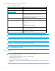
6 Using the event log This chapter provides information on viewing the event log and contains the following sections: • Event messaging in XPath OS, next • Viewing the event log, page 72 • Adding and deleting syslog hosts, page 73 Event messaging in XPath OS Event messages provide information regarding the status of the switch and ports; each message has a severity level. The event log saves all messages generated by the system since the last reboot.
Table 3 Event message levels (continued) Event level Description 4 = Info Info messages report the current status of the system components other than error status. For example, detecting on and off line status of a fabric port. 5 = Debug Debug messages are for debugging use only. They are produced by code inserted by the vendor to inform the user that a suspected problem has occurred.
3. Click Filter in the task bar. 4. Select the filter criteria: • To show all events occurring after a specified date and time: a. Select the From checkbox to activate this filter. b. Select the starting date from the drop-down menu in the leftmost From box. The drop-down menu contains a calendar from which you can select the date. You can also enter the date in the boxes. c. Enter the starting time in the rightmost From box. The time is in the format hh:mm.
Using the event log
7 Managing Fibre Channel frame routing There are two major aspects of Fibre Channel frame routing that you can control: whether frames must be delivered in order and whether dynamic load-sharing path calculations are permitted. You can also view path and port routing information.
Enabling and disabling in-order frame delivery In a stable fabric, frames are always delivered in order, even when the traffic between switches is shared among multiple paths. However, when topology changes occur in the fabric (for instance, a link goes down), traffic is rerouted around the failure. When topology changes occur, some frames can be delivered out of order. Enabling in-order delivery (IOD) guarantees that frames are either delivered in order or dropped.
6. Select the load sharing option: • Select Dynamic Load Sharing to enable DLS. • Clear Dynamic Load Sharing to disable DLS. 7. Click OK. Viewing FSPF routes The FSPF Routes pane displays the FSPF routes (see Figure 27) and the following information about each route: In Port Name The name of the port from which a frame comes. In Port# The number of the port from which a frame comes. Destination Domain The destination domain of the incoming frame.
Figure 27 Administration page with Routing tab and FSPF Routes subtab selected Managing static routes You can view and manage static routes through the Static Routes subtab, as shown in Figure 28. The Static Routes pane displays the following information about each route: 78 In Port Name The name of the port from which a frame comes. In Port# The number of the port from which a frame comes. Destination Domain The destination domain of the incoming frame.
Figure 28 Administration page with Routing tab and Static Routes subtab selected Configuring a static route Use the following procedure to add a static route: 1. Access the Switch Manager. 2. Click Administration in the navigation bar. 3. Click the Routing tab. 4. Click the Static Routes subtab. 5. Click Add in the task bar. The Add Static FC Route dialog box opens. 6. Select the input port from the drop-down list. 7. Enter the destination domain ID. 8. Select the output port from the drop-down list. 9.
4. Click the Static Routes subtab. 5. Select the route to delete. 6. Click Delete in the task bar. 7. Click Yes in the confirmation window. Configuring link cost The cost of a link is used to determine the least-costly path for a frame from the source to the destination switch. The cost of a path is the sum of the costs of all the ISLs traversed by that path. Every ISL has a default cost that is inversely proportional to its bandwidth.
Figure 29 Administration page with Routing tab and Link Cost subtab selected Advanced Web Tools 7.4.
Managing Fibre Channel frame routing
8 Monitoring performance This chapter contains the following sections: • Monitoring performance with Advanced Web Tools, next • Configuring the performance table, page 84 • Refreshing the ports and counters table, page 85 • Changing the autorefresh interval, page 85 • Changing the counter values, page 85 • Configuring performance charts, page 86 Monitoring performance with Advanced Web Tools You can monitor performance through the Switch Manager.
Figure 31 Performance page with Charts tab selected Configuring the performance table You can customize the performance information to be displayed by selecting the ports you want to monitor and the counters to be included in the table. Selecting the ports and counters to monitor 1. From the Switch Explorer, click the Perf icon in the Switch View, or from the Switch Manager, click Performance in the navigation bar. 2. Click the Counters tab. 3. Click Select Ports and Counters in the task bar. 4.
Refreshing the ports and counters table If the Refresh Counters task is grayed out, it means that autorefresh is enabled and the display is refreshed after a specified number of seconds. To disable autorefresh or to change the refresh interval, see the section “Changing the autorefresh interval,” next. Refreshing the counter display and charts 1. From the Switch Explorer, click the Perf icon in the Switch View or from the Switch Manager, click Performance in the navigation bar. 2.
Configuring performance charts The number of charts displayed depends on the chart configuration you select. You can select multiple charts to be displayed or a single chart to display all the performance statistics. The maximum number of charts that can be displayed is 16. If you select a combination of ports and counters that results in a number of charts exceeding the maximum, an error message appears, asking you to reduce the number of ports and counters selected.
9 Using the FC-FC Routing service This chapter provides the procedures for managing Fibre Channel routing using Advanced Web Tools. It contains the following sections: • Managing FC-FC Routing with Advanced Web Tools, next • Setting up a meta-SAN with an MP Router, page 92 • Configuring a backbone fabric, page 92 For background information on Fibre Channel routing, see the HP StorageWorks XPath OS 7.4.x administrator guide.
Viewing and configuring EX_Port information The EX_Ports tab (see Figure 33) displays the EX_Ports, including configuration and status information. You can also view this information from the Ports page. To configure the EX_Ports, use the same procedures described in ”Managing ports” on page 45, The EX_Port tasks that are listed in the task bar are the same as those tasks described in ”Managing ports” on page 45.
Viewing edge fabric information The Edge Fabric tab (see Figure 34) lists all the edge fabrics visible to the MP Router. The table displays the following information about each edge fabric: ID The fabric ID of the edge fabric. Type The type of edge fabric. Values are Local and Remote. Edge Domain The domain name of the edge fabric. Edge WWN The WWN of the switch of the edge fabric.
Figure 35 FC Routing page with the LSAN Zones tab selected Viewing LSAN devices The LSAN Devices tab (see Figure 36) lists all the LSAN devices. An LSAN device can be a physical device, meaning that it physically exists in the fabric, or it can be a proxy device. A proxy device represents a real device on another edge fabric. It has a Name Server entry and is assigned a valid port ID. When a proxy device is created in a fabric, the real device is considered to be imported into that fabric.
Figure 36 FC Routing page with LSAN Devices tab and Physical subtab selected Proxy devices The Proxy pane (shown in Figure 37) displays the following information about each proxy LSAN device: Port WWN The WWN of the device port. Proxy Fabric The fabric ID of the edge fabric in which this device is a proxy. Proxy PID The port ID of the proxy device. Physical Fabric The fabric ID of the edge fabric in which this device physically exists. Physical PID The port ID of the corresponding physical device.
Figure 37 FC Routing page with LSAN Devices tab and Proxy subtab selected Setting up a meta-SAN with an MP Router Use the following procedure to set up a meta-SAN with an MP Router: 1. Stop all FCR ports (see ”Starting and stopping a port” on page 51). 2. Connect the MP Routers to the edge fabrics and backbone fabric, if used. 3. Install or verify the Fibre Channel Routing Services license (see ”Verifying, installing, and removing licenses” on page 34). 4.
Use the following procedure to configure a backbone fabric: 1. Access the Switch Manager. 2. Click FC Routing in the navigation bar. 3. Click the General tab. 4. Click Set Fabric ID in the task bar. The Set Backbone Fabric ID window opens. 5. Enter a fabric ID for the backbone fabric. The fabric ID is a number from 1 through 128. 6. Click OK. Advanced Web Tools 7.4.
Using the FC-FC Routing service
10 Using exchange-based trunking This chapter provides information on managing exchange-based trunking on a switch. The trunking feature is disabled by default and can be enabled only after the trunking license is installed. Verify and install the trunking license using the procedures described in ”Verifying, installing, and removing licenses” on page 34. For background information on exchange-based trunking, see the HP StorageWorks XPath OS 7.4.x administrator guide.
Figure 38 Administration page with the Trunking Information tab selected 96 Using exchange-based trunking
11 Managing the iSCSI Gateway The HP iSCSI Gateway Service facilitates communication between TCP/IP networks and Fibre Channel SANs and displays iSCSI gateway configuration information across multiple MP Routers.
Viewing and configuring iSCSI ports The iSCSI Ports tab (see Figure 40) displays the iSCSI ports, including configuration and status information. You can also view this information from the Ports page. To configure the iSCSI ports, use the same procedures described in ”Managing ports” on page 45. The iSCSI port tasks that are listed in the task bar are the same as those tasks described in ”Managing ports” on page 45.
Connected to The domain and port that the iSCSI name translation is assigned (iSCSI port). Initiator? Indicates whether this is an initiator, a target, or unknown. Physical? Indicates whether this is a physical or a virtual device. Transport The type of transport used, such as iSCSI or FCP. Symbolic Name The symbolic name of Fibre Channel target. Node WWN The WWN of the iSCSI device.
2. Optional: Zoning-based access control is required, but you can also use iSCSI shared secrets (that is, CHAP, access control) for enhanced security. If you choose to configure CHAP access control, see ”Configuring CHAP” on page 100 to configure the shared secret for the Fibre Channel targets. When you configure the iSCSI initiator driver, you define the shared secret for the initiator. 3. Configure the iSCSI gateway ports using the procedure in ”Configuring a port” on page 46. 4.
Figure 42 Config iSCSI Initiator window 5. To add an iSCSI initiator, enter the name in the iSCSI Name box and enter the CHAP secret in the CHAP Secret box. To add or modify the CHAP secret of an existing iSCSI initiator, select the name from the table at the top of the window, and enter the CHAP secret in the CHAP Secret box. To delete the CHAP secret of an existing iSCSI initiator, select the name from the table at the top of the window, and clear the CHAP secret in the CHAP Secret box.
6. Click the Add/Update button. 7. Repeat step 5 and step 6 until you have finished configuring iSCSI targets. 8. Click Close. Monitoring iSCSI performance You can monitor the iSCSI performance through the Performance page by including iSCSI counters in performance charting. See ”Monitoring performance” on page 83, for more information.
12 Notes on Advanced Web Tools The following sections describe limitations and other information that you should be aware of: • Browser limitations, next • Java Plug-in limitations, page 103 • Online help issue, page 103 Browser limitations The following is a known limitation in Advanced Web Tools, relevant to the browser: Launching a telnet session from Advanced Web Tools on a Solaris or Linux system when using a Mozilla browser is not supported, due to technical limitations in Mozilla.
Notes on Advanced Web Tools
A Summary of Switch Manager pages This appendix lists the Switch Manager pages and tabs, and briefly describes what you can do on each page and tab. Application page Summary View MP Router information. Turn the beacon on and off. Open a telnet window. Details View status of power supplies, temperature sensors, and fans. View configuration and status information for the MP Router module. Ports page (All tabs) View and edit port configuration information. Rename port. Start and stop port.
Zone Aliases View list of zone aliases in fabric. Create new zone aliases. Delete, rename, and clone zone aliases. Save all zone configuration information. Zone Configurations View list of zone configurations in fabric. Create new zone configurations. Delete, rename, and clone zone configurations. Enable and disable zone configurations. Save all zone configuration information. Administration page Switch Information Enable and disable MP Router. Reboot the MP Router. Rename the MP Router.
iSCSI Gateway page General Display general information about the iSCSI gateway. iSCSI Ports View and edit iSCSI port configuration information. Rename iSCSI port. Start and stop iSCSI port. Enable and disable iSCSI port. iSCSI Devices View list of iSCSI initiators and targets. Add a new iSCSI initiator. Configure CHAP secrets for initiators or targets. FC Routing page General Set the fabric ID. EX_Ports View and edit EX_Port configuration information. Rename EX_Port. Start and stop EX_Port.
Summary of Switch Manager pages
B Telnet command equivalents If you are already familiar with the XPath OS telnet commands and want a quick reference as to how to perform the same function using Advanced Web Tools, see Table 4. This table lists XPath OS telnet commands and gives the corresponding Advanced Web Tools procedure. The commands are listed in alphabetical order.
Table 4 Telnet commands and Advanced Web Tools equivalents (continued) Telnet command Advanced Web Tools equivalent cfgActvShow Zoning page, Zone Configurations tab Click the effective zone configuration name to open the drill-down page. cfgAdd Zoning page, Zone Configurations tab Click a zone configuration name to open the drill-down page. Click the Add Member task. cfgClear Zoning page, Zone Server tab Click the Purge task. cfgCreate Zoning page, Zone Configurations tab Click the New task.
Table 4 Telnet commands and Advanced Web Tools equivalents (continued) Telnet command Advanced Web Tools equivalent diagDisablePost No corresponding Advanced Web Tools equivalent. diagEnablePost No corresponding Advanced Web Tools equivalent. diagHelp No corresponding Advanced Web Tools equivalent. diagPortMailbox No corresponding Advanced Web Tools equivalent. diagPortMem No corresponding Advanced Web Tools equivalent. diagPortMemArm No corresponding Advanced Web Tools equivalent.
Table 4 Telnet commands and Advanced Web Tools equivalents (continued) Telnet command Advanced Web Tools equivalent fazoneCreate Zoning page, Zones tab Click the New task. fazoneDelete Zoning page, Zones tab Select a zone and click the Delete task. fazoneRemove Zoning page, Zones tab Click a zone name to open the drill-down page. Select a member and click the Remove Members task. fazoneShow Zoning page, Zones tab fcipShow Ports page, FCIP Ports tab Click a port name to open the drill-down page.
Table 4 Telnet commands and Advanced Web Tools equivalents (continued) Telnet command Advanced Web Tools equivalent ipaddrShow Administration page, Network Config tab iscsiAuthCfg iSCSI Gateway page, General tab iscsiFailoverAdd No corresponding Advanced Web Tools equivalent. iscsiFailoverDelet e iscsiPortShow No corresponding Advanced Web Tools equivalent. For port statistics: Performance page, Counters tab. Click Select Ports and Counters to configure iSCSI ports and performance counters.
Table 4 Telnet commands and Advanced Web Tools equivalents (continued) Telnet command Advanced Web Tools equivalent portCfgNPort Ports page, All Ports tab Select a port and click the Edit Configuration task. portCfgSpeed Ports page, FC Ports tab Select a port and click the Edit Configuration task. portCfgTopology Ports page, FC Ports tab Select a port and click the Edit Configuration task. portDiagClear No corresponding Advanced Web Tools equivalent.
Table 4 Telnet commands and Advanced Web Tools equivalents (continued) Telnet command Advanced Web Tools equivalent qloopShow No corresponding Advanced Web Tools equivalent. quit No corresponding Advanced Web Tools equivalent. reboot Administration page, Switch Information tab Click the Reboot task. rnPing No corresponding Advanced Web Tools equivalent. routeShow No corresponding Advanced Web Tools equivalent. secAuthSecret No corresponding Advanced Web Tools equivalent.
Table 4 Telnet commands and Advanced Web Tools equivalents (continued) Telnet command Advanced Web Tools equivalent topologyShow Fabric page trunkReset Administration page, Trunking tab Click the Disable task. trunkSet Administration page, Trunking tab Click the Enable task. trunkShow Administration page, Trunking tab tsClockServer No corresponding Advanced Web Tools equivalent. upTime Administration page, Switch Information tab See Boot Time in the Switch table.
Glossary alias A logical grouping of elements in a fabric. An alias is a collection of port numbers and connected devices, used to simplify the entry of port numbers and WWNs when creating zones. area number In Fabric OS 4.0 and later, ports on a switch are assigned a logical area number. Port area numbers can be viewed by issuing the switchShow command. They are used to define the operative port for many Fabric OS commands, for example, area numbers can be used to define the ports within an alias or zone.
configuration 1. A set of parameters that can be modified to fine-tune the operation of a switch. Use the configshow command to view the current configuration of the switch. 2. In HP StorageWorks Zoning, a zoning element that contains a set of zones. The configuration is the highest-level zoning element and is used to enable or disable a set of zones on the fabric. See also zone configuration. core PID Core switch port identifier. The core PID must be set for Fabric OS 3.
error With respect to the Fibre Channel industry, a missing or corrupted frame, timeout, loss of synchronization, or loss of signal (link errors). EX_Port A type of E_Port that connects an FC router to an edge fabric. EX_Ports limit the scope of fabric services, but provide device connectivity using FC-NAT. fabric A collection of Fibre Channel switches and devices, such as hosts and storage. Also called a switched fabric. See also SAN, topology.
FID Fabric ID. Unique identifier of a fabric in a meta-SAN. firmware The basic operating system provided with the hardware. FL_Port Fabric loop port. A port that is able to transmit under fabric protocol and also has arbitrated-loop capabilities. Can be used to connect an NL_Port to a switch. See also F_Port, Fx_Port. F_Port Fabric port. A port that is able to transmit under fabric protocol and interface over links. Can be used to connect an N_Port to a switch. See also FL_Port, Fx_Port.
interswitch link See ISL. IOD In-order delivery. A parameter that, when set, guarantees that frames are either delivered in order or dropped. IP Internet Protocol. The addressing part of TCP. IQN iSCSI qualified name. iSCSI Internet Small Computer Systems Interface. A protocol that defines the processes for transferring block storage applications over TCP/IP networks by encapsulating SCSI commands into TCP and transporting them over the network by IP. See also SCSI.
meta-SAN The collection of all devices, switches, edge and backbone fabrics, LSANs, and FC routers that make up a physically connected but logically partitioned storage network. LSANs span between edge fabrics using FC routers. In a data network, this would simply be called the network.
port name A user-defined alphanumeric name for a port. POST Power-on self-test. A series of tests run by a switch after it is turned on. principal switch The first switch to boot up in a fabric. Ensures unique domain IDs among roles. protocol A defined method and set of standards for communication. Determines the type of error-checking, the data-compression method, how sending devices indicate an end of message, and how receiving devices indicate receipt of a message.
SNMP Simple Network Management Protocol. An Internet management protocol that uses either IP for network-level functions and UDP for transport-level functions, or TCP/IP for both. Can be made available over other protocols, such as UDP/IP, because it does not rely on the underlying communication protocols. See also community (SNMP). switch name The arbitrary name assigned to a switch. switch port A port on a switch. Switch ports can be E_Ports, F_Ports, or FL_Ports. See also E_Port, F_Port, FL_Port.
U_Port Universal port. A switch port that can operate as a G_Port, E_Port, F_Port, or FL_Port. A port is defined as a U_Port when it is not connected or has not yet assumed a specific function in the fabric. WWN World wide name. An identifier that is unique worldwide. Each entity in a fabric has a separate WWN. zone A set of devices and hosts attached to the same fabric and configured as being in the same zone.
Index A accessing Switch Manager 15 adding licenses 13, 35 syslog hosts 73 trap recipient 42 users 36 Administration page 22, 106 Application page 105 audience 7 authorized reseller, HP 9 B backbone fabrics, configuring 92 BB credit, configuring 22 beaconing, turning on and off 39 browser limitations 103 browsers, supported 12 C Change Domain Id window 27 changing passwords 36 CHAP secret, configuring 100 Clone Zone Alias window 60 Clone Zone Confirmation window 67 Clone Zone window 64 cloning zone alias
E I E_D_TOV, configuring 23 edge fabrics, viewing 89 Edit Fibre Channel Configuration window 26 Edit Port Configuration window 47, 48 Edit Zone Server Attributes window 69 Enable Application Platform window 38 Enable Port window 52 enabling dynamic load sharing 76 exchange-based trunking 95 FCIP tunneling 49 in-order frame delivery 76 MP Router 37 ports 52 zone configurations 68 Error Log window 17 Ethernet management ports, configuring 33 event log about 71 message levels 71 viewing 72 Events page 105 ev
monitoring iSCSI performance 102 monitoring performance 83 MP Router disabling 38 enabling 37 managing 31 rebooting 38 renaming 38 N Name Server page 105 New Zone Alias window 59 New Zone Confirmation window 66 O opening a Telnet window 32 operating systems, supported 12 P pages Administration 22, 106 Application 105 drill-down 17 Events 105 Fabric 105 FC Routing 107 iSCSI Gateway 107 Name Server 105 Performance 106 Ports 105 top-level 17 Zoning 105 passwords changing 36 resetting 37 performance charts c
components 17 main window 16 navigation bar 17 symbols in text 8 syslog hosts, adding and deleting 73 Change Domain Id 27 Clone Zone 64 Clone Zone Alias 60 Clone Zone Confirmation 67 Confirm Potential Disruption 48 Confirmation 35 Disable Application Platform 38 Disable Port 53 Edit Fibre Channel Configuration 26 Edit Port Configuration 47, 48 Edit Zone Server aAtributes 69 Enable Application Platform 38 Enable Port 52 Error Log 17 Login 19 New Zone Alias 59 New Zone Confirmation 66 Reboot Switch 38 Rename
hard 56 introduction to 55 soft 57 terminology 55 Advanced Web Tools 7.4.