
HP StorageWorks MSA Hub 2/3 Replacement Instructions (April 2004)
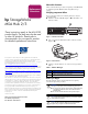
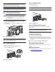
Table Of Contents
Caution: It is important to follow these instructions when replacing
components in the MSA. If the procedure is done improperly, it is
possible to lose data or damage equipment.
Note: Before replacing the MSA Hub 2/3 it is important to stop all system
access (e.g. application, system I/O or RAW device file path/s) to the
device.
Step 1: Removing the SFP transceiver
WARNING: To reduce the risk of injury from laser radiation or
damage to the equipment, observe the following precautions:
■ Do not open any panels, operate controls, make adjustments,
or perform procedures to a laser device other than those
specified herein.
■ Do not stare into the laser beam when panels are open.
1. Press the release clip on the bottom of the cable connector 1 to
remove the Fibre Channel cable.
2. Pull the transceiver out of the device by pulling up and out on the
plastic tab 2.
Figure 3: Removing the SFP transceiver
Caution: Touching the end of a fibre cable damages the cable.
Whenever a fibre cable is not connected, replace the protective
covers on the ends of the cables.
Step 2: Removing the hub
To remove the hub (see Figure 4):
1. Slide the port-colored release latch 1 to the right.
2. Slide the hub 2 straight out.
Figure 4: Removing the hub
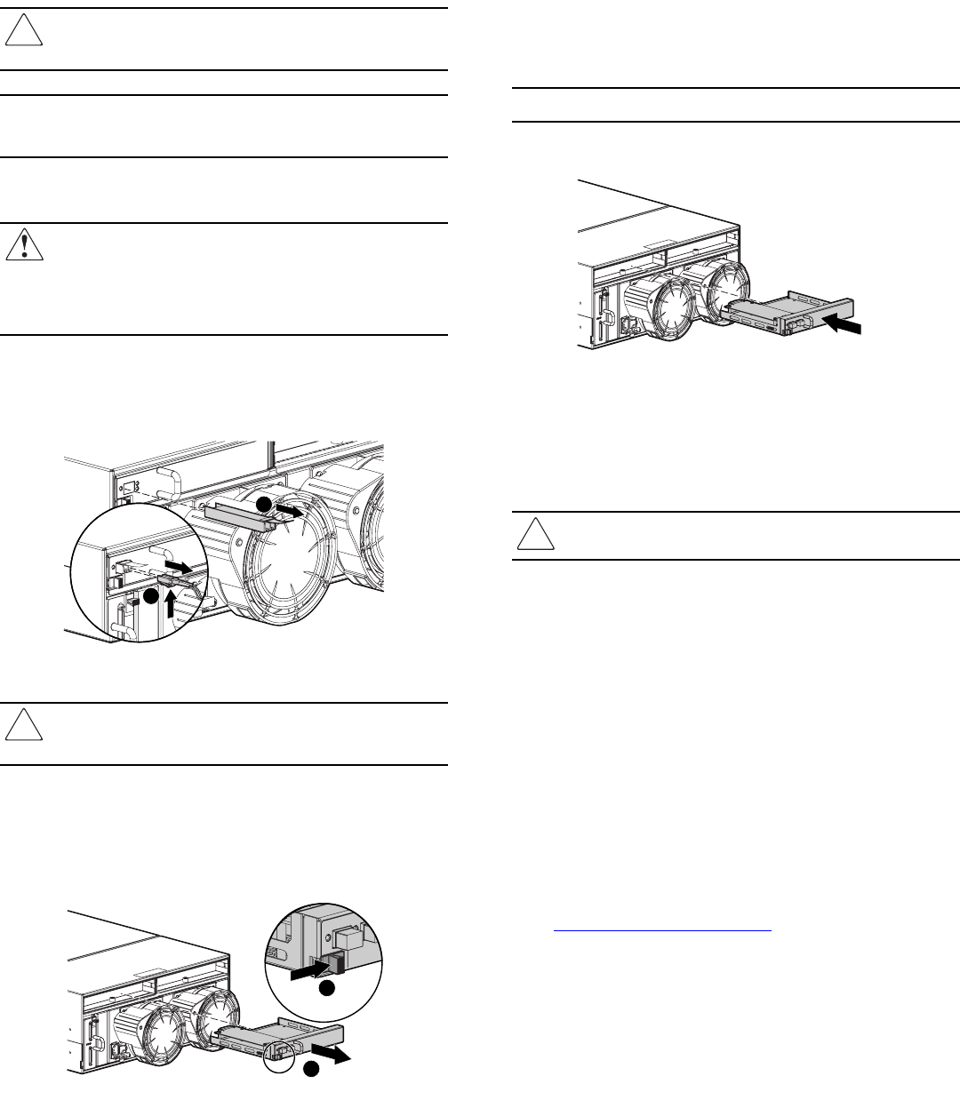
Step 3: Installing the hub
To install the new hub:
1. Slide the hub straight in.
Note: The release latch should automatically close.
2. Make sure the release latch has closed and is secure.
Figure 5: Installing the hub
Step 4: Installing the SFP transceiver
Insert the SFP transceiver into the new hub and replace the Fibre
Channel cable.
Caution: To reduce the risk of damage to the equipment, do not
use excessive force when inserting the transceiver.
Installation is complete.
Verifying the replacement
After replacing the failed hub verify that:
■ Check the controller fault LED (Figure 1, 1) to be sure that the
LED is off. Unread error log messages may cause the LED to
remain lit. Be sure all error messages that have been responded to
are deleted.
■ The service indicator LED (Figure 2, 1) is solid green.
■ No new error messages are displayed on the LCD.
Returning the failed component
Please follow the return instructions provided in the new component
package.
Additional information
For additional information, refer to the MSA technical documents web
site at
http://www.hp.com/go/msa1000
.
15096
2
1
1
2
15074
15075