getting started guide hp surestore fc 1Gb/2Gb entry switch 8B and fc 1Gb/2Gb switch 8B www.hp.
Notice Safety notices © Hewlett-Packard Company, 2001. All rights reserved. Any servicing, adjustment, maintenance, or repair must be performed only by authorized service-trained personnel. Part number: A7346-96002 Edition: E1201 Format conventions Hewlett-Packard Company makes no warranty of any kind with regard to this material, including, but not limited to, the implied warranties of merchantability and fitness for a particular purpose.
CONTENTS Revision History . . . . . . . . . . . . . . . . . . . . . . . . . . . . . . . . . . . . . . . . . . . . v Updates . . . . . . . . . . . . . . . . . . . . . . . . . . . . . . . . . . . . . . . . . . . . . . . . . . . v Related Publications . . . . . . . . . . . . . . . . . . . . . . . . . . . . . . . . . . . . . . . . . v 1 Installing the Switch . . . . . . . . . . . . . . . . . . . . . . . . . . . . . . 1 Product Description . . . . . . . . . . . . . . . . . . . . . . . . . . . . . . . . . . .
Next Steps . . . . . . . . . . . . . . . . . . . . . . . . . . . . . . . . . . . . . . . . . . . . . . . . Setting QuickLoop Mode on Ports . . . . . . . . . . . . . . . . . . . . . . . . . . Setting Up Speed Negotiation . . . . . . . . . . . . . . . . . . . . . . . . . . . . . . Configuring Supported Devices . . . . . . . . . . . . . . . . . . . . . . . . . . . . 3 Diagnostics . . . . . . . . . . . . . . . . . . . . . . . . . . . . . . . . . . . . 35 Switch Status Indicators . . . . . . . . . . . . . . .
Revision History December 2001 First release. Updates For the most current information about the HP Surestore FC 1Gb/2Gb Entry Switch 8B and FC 1Gb/2Gb Switch 8B, visit the support Web site located at http://www.hp.com/support/fc8B. For information about product availability, configuration, and connectivity, consult your HP account representative. Related Publications Related product information can be found in the following publications.
Title Part Number Web Tools User’s Guide, version 3.0 Available on CD Distributed Fabrics User’s Guide, version 3.0 Available on CD Zoning User’s Guide, version 3.0 Available on CD MIB Reference Manual, version 3.0 Available on CD ISL Trunking User’s Guide, version 3.0 Available on CD Advanced Performance Monitoring User’s Guide, version 3.
1 INSTALLING THE SWITCH Product Description The FC Entry Switch 8B and FC Switch 8B products are 8-port Fibre Channel gigabit switches that support link speeds up to 2 Gbps. Each port automatically negotiates to the highest common speed of all devices connected to the port.
Safety Guidelines Follow these safety guidelines to ensure successful and safe operation of the switch: • The supply circuit, line fusing, and wire size must conform to the electrical rating on the switch nameplate. • The ambient air temperature near the switch must not exceed 40 degrees Celsius. This is particularly important to verify if the switch is installed in a closed or multi-rack assembly.
Package Contents The major items included in the shipping carton(s) include the following items: • One FC Entry Switch 8B or FC Switch 8B • One 10 ft. RS-232 serial cable (convertible to an RJ-45 connector by removing the adapter on the end of the cable) • One grounded 6 ft.
a. Clean the four depressions on each bottom corner of the switch to ensure they are free of dust. b. Place a rubber foot in each depression with the adhesive side against the chassis and press into place. 3. Place the switch with the bottom side down on a flat, sturdy surface. 4. Provide power to the switch by connecting the power cord to the switch power supply and to a power outlet. Ensure the power cord is routed so that it is not exposed to stress.
The following items are required to install the switch in a rack: • FC Entry Switch 8B or FC Switch 8B • Power cable • #2 Phillips and T25 Torx screwdrivers • Plenum • Rails and rail mounting hardware: (2) Rear mounting bracket (8) #8-32 x 5/16 Phillips pan-head screw with captive star lock washer (8) #8 Flat washer (6) M5 Torx head screw with captive lock washer (2) Rubber washer (4) M5 U-type Tinnerman clip (HP rack only) (4) #10-32 square Tinnerman nut (Compaq/Rittal rack only) (4) #10-32 x 5/8 P
(6) Spacer (Compaq/Rittal rack only) (4) M5 flat washer (Compaq/Rittal rack only) For proper airflow, the SFP media side of the FC Entry Switch 8B or FC Switch 8B faces the rear of the rack. This mounting allows air to enter the front of the rack through the plenum and to exhaust at the rear of the rack, similar to other rack-mounted equipment. This prevents switch overheating that may cause it to fail. CAUTION To install the switch in an HP rack: 1.
Figure 2. Installing the Rear Rail-Tray Brackets 4. Install two M5 U-type Tinnerman clips for each of the front columns of the rack in the top and bottom positions of the three-hole EIA pattern as shown in Figure 3.
Figure 3. Installing the Tinnerman Clips 5. Assemble the outer rails by completing the following steps: a. As an aid in assembly, two rubber washers have been included to help keep the rear slotted portion of the outer rail flush against the rear rail-tray brackets. Install them as shown in Figure 4.
Figure 4. Installing the Rubber Washers b. Insert the alignment pins attached to the outer rail front flange into the center opening in the rack. c. Install one M5 Torx screw in the upper hole location of the right rail. Then, install one M5 Torx screw in the lower location of the left rail. See Figure 5. Note Installing the Switch Do not install the upper left and lower right screws until later.
Figure 5. Assembling the Outer Rails 6. Assemble each of the two inner rails (one on each side of the switch and plenum) using eight #8-32 x 5/16 Phillips pan-head screws (with attached star lock washers) and eight #8 flat washers as shown in Figure 6. Do not use any other screws other than the eight that are provided. Use of any longer lengths can cause damage to internal components of the switch. Be sure to install the flat washers along with the pan-head screws.
Figure 7. Installing the Switch into an HP Rack 8. Install the two remaining M5 Torx screws into the upper left and lower right holes to complete the installation. See Figure 8.
Figure 8. Securing the Switch 9. Provide power to the switch by connecting the power cord to the switch power supply and to a power outlet. Ensure the power cord is routed so that it is not exposed to stress. Power is supplied to the switch as soon as the cord is connected. The switch runs POST (power on self-test) by default each time it is turned on. Note Do not connect the switch to the network until the IP address is correctly set.
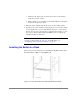
3. Attach the rear rail-tray brackets to the rear rack uprights by assembling each of the two brackets with two spacers, two M5 flat washers, and one M5 Torx head screw with captive lock washer as shown in Figure 9. Note The alignment pins will be resting on the top surfaces of the spacers. Figure 9. Installing the Rear Rail-Tray Brackets 4. Install two #10-32 square Tinnerman nuts for each of the front columns of the rack in the top and bottom positions of the three-hole EIA pattern.
Figure 10. Installing the Tinnerman Nuts and Spacers 5. Assemble the outer rails by completing the following steps: a. As an aid in assembly, two rubber washers have been included to help keep the rear slotted portion of the outer rail flush against the rear rail-tray brackets. Install them as shown in Figure 11.
Figure 11. Installing the Rubber Washers b. Insert the alignment pins attached to the outer rail front flange into the center opening in the rack. Note The alignment pins will be resting on the top surfaces of the spacers. c. Install one #10-32 x 5/8 Phillips pan-head screw in the upper hole location of the right rail. Then, install one #10-32 x 5/8 Phillips pan-head screw in the lower location of the left rail as shown in Figure 12.
Figure 12. Assembling the Outer Rack 6. Assemble each of the two inner rails (one on each side of the switch and plenum) using eight #8-32 x 5/16 Phillips pan-head screws (with attached star lock washers) and eight #8 flat washers as shown in Figure 13. Do not use any other screws other than the eight that are provided. Use of any longer lengths can cause damage to internal components of the switch. Be sure to install the flat washers along with the pan-head screws.
Figure 13. Assembling the Inner Rails 7. Insert the switch with the attached inner rails into the outer rails as shown in Figure 14. Figure 14. Installing the Switch into a Compaq/Rittal Rack 8. Install the remaining #10-32 x 5/8 Phillips pan-head screws into the upper left and lower right holes to complete the installation. See Figure 15.
Figure 15. Securing the Switch 9. Provide power to the switch by connecting the power cord to the switch power supply and to a power outlet. Ensure the power cord is routed so that it is not exposed to stress. Power is supplied to the switch as soon as the cord is connected. The switch runs POST (power on self-test) by default each time it is turned on. Note Do not connect the switch to the network until the IP address is correctly set.
2 SETUP System Components The FC Entry Switch 8B or FC Switch 8B consists of the following components: • A chassis designed to be mounted in a 1U rack space, with forced-air cooling that flows from the fan side of the switch to the cable side. • Eight optical ports, compatible with SFP (small form factor pluggable) media. • One RS-232 serial port (DB9 connector) on the SFP media side. • One IEEE compliant RJ-45 connector on the SFP media side for use with 10/100 Mbps Ethernet or in-band.
– One LED in the center of the fan side to indicate the overall switch status. • One universal input power supply. • Five fans: – Two dedicated to cooling the power supply, three dedicated to cooling the motherboard. – Air is pulled in through the rear intake and pushed out through the vents in the SFP media side. • Three digital thermometers, capable of sensing a temperature range from -55°C to +125°C, in 0.5°C increments. • A real-time clock (RTC) with a 10-year battery and 56 bytes of NVRAM.
Note ISL Trunking is a Fabric OS feature that enables distribution of traffic over the combined bandwidth of up to four ISLs between two directly adjacent switches, while preserving in-order delivery. For information about ISL Trunking, refer to the ISL Trunking User’s Guide. Fan Side Figure 17 shows the fan side of the switch, which contains the fans and the switch status LED. Figure 17.
Note Removing all power from the switch triggers a system reset. When power is restored, all devices are returned to the initial state and the switch runs POST, a system check that lasts approximately 2.5 minutes. POST can be skipped by using the fastboot command. For more information about this command, refer to the Fabric OS Reference Manual. A fast boot requires approximately two minutes to complete. Fabric Operating System Included with the switch is the Fabric OS.
To connect an SC cable to the FC Entry Switch 8B or FC Switch 8B, use the HP C7540A - 2M LC male - SC male cable adapter. Connect inter switch links (ISLs) between two FC Entry Switch 8B or FC Switch 8B products using an LC to LC cable. Table 1.
• Workstation that has a terminal emulator application (such as HyperTerminal) • Serial cable provided with the switch for connecting the switch to the workstation • An unused IP address • Ethernet cable for connecting the switch to the workstation or to a network containing the workstation • SFPs and FC cables as required to connect the switch to the fabric To configure the switch and connect it to a fabric: 1.
– In a UNIX environment, enter the following string at the prompt: tip /dev/ttyb -9600. f. From the terminal emulator application, log on to the switch with administrative privileges through the serial connection. The default administrative logon is admin and the default password is password. Do not change the default password unless local administration policy requires it. CAUTION g. Enter the following at the terminal emulator application prompt: ipAddrSet. h.
Note The serial port is intended only for use during the initial setting of the IP address and for service purposes. Using the serial port during normal switch operation or for regular maintenance is not recommended. 2. Connect the switch to the workstation computer by Ethernet cable (can be a direct connection or through a network). a. Remove the shipping plug from the Ethernet port. b. Insert one end of an Ethernet cable in the Ethernet port. c.
b. Then enter the following to display the configuration prompts: configure. c. Enter “y” after the prompt “Fabric parameters”. For example: Fabric parameters (yes, y, no, n): [no] y d. Enter a unique domain ID: Domain: (1..239) [1] 3. e. Complete the remaining prompts or press CTRL+D to accept the remaining settings without completing all the prompts. f. Re-enable the switch by entering the following: switchEnable. 5.
the SFP until it is firmly seated and the latching mechanism clicks. For instructions specific to the cable type, refer to the cable manufacturer’s documentation. Note The cables used in trunking groups must meet specific requirements. For a list of these requirements, refer to the ISL Trunking User’s Guide. The cable is keyed so that it can only be inserted correctly into the SFP. If the cable does not slide in easily, ensure it is correctly oriented. 8.
1. Verify that the RSHD service (on a UNIX machine) or the FTP service (on a Windows machine) is running on the host workstation. 2. Log on to the switch as the admin user. 3.
system configuration file, and password is the password for the user ID specified. Note The password operand is only required if you are using FTP. 5. Reboot the switch by entering the following command: fastBoot Next Steps Specific tasks remain to be completed before the switch is fully operational and manageable in your network with your equipment. These tasks and the associated tools are described in the remaining documents shipped with the product on the Documentation CD.
switchCfgSpeed. To set the speed level for a single port, use the portCfgSpeed. Depending on your environment you may need to force a port to use a specific speed level. Auto negotiation may not be supported by the device. Check the configuration information for your network components for specific requirements. See the Fabric OS Reference Manual for a detailed command description.
Step 12: Complete Zoning Activities Step 13: Save Active Zone Set For complete instructions on configuring the HP Director FC-64 switch see “Checklist for Merging Fabrics” in the Merging Heterogeneous Fabrics Instructions white paper on the FC Entry Switch 8B or FC Switch 8B Documentation CD. HP Surestore VA 7400 The FC Entry Switch 8B or FC Switch 8B also can support a 2Gb connection to an HP Surestore Virtual Array 7400. Set the port speed to 2Gb using the telnet command portCfgSpeed.
Private Loop Devices To work with private loop devices such as the FC 60, the FC 10, or the SCSI bridge FC 4/2, set the FC Entry Switch 8B or FC Switch 8B port as an L_PORT. See the telnet command portCfgLport.
34 Getting Started Guide
3 DIAGNOSTICS Switch Status Indicators System activity and status can be determined through the activity of the LEDs on the switch. The LEDs may flash yellow during diagnostic tests, and green, yellow, or orange during POST. This is normal, and does not indicate a problem unless the LEDs do not display a healthy pattern after POST or the other diagnostic tests are complete. Note The orange light may be referred to as “amber” in other documentation.
• Two Ethernet port LEDs, one to show link speed and one to show link status. LEDs on the SFP Media Side Figure 18 shows the SFP media side of the switch with the LEDs identified. Figure 18. The SFP Media Side of the FC Entry Switch 8B and FC Switch 8B The LEDs may flash different colors during diagnostic tests and POST. This does not indicate a problem unless the LEDs do not display a healthy pattern after POST or the other diagnostic tests are complete.
Color of LED Status of Hardware Recommended Action Steady yellow One or more ports are not ready for use. Switch may be booting or disabled, or one or more ports may be faulty. Verify that the switch has completed booting and is not disabled. If the light is still yellow, check the port status LEDs. Slow-flashing yellow One or more ports are faulty. Check the port status LEDs. Also, any errors are listed in the error log.
Color of LED Status of Hardware Recommended Action Flickering green Port is online, with traffic flowing through port. No action required. Steady orange Port is receiving light or signal No action required. carrier, but is not yet online. Slow-flashing orange (on 1 second; off 1 second) The port is disabled (result of diagnostics or portDisable command). Reset the port from a management station. Fast-flashing orange (on 1/4 second; off 1/4 second) The port is faulty.
Color of LED Status of Hardware Recommended Action No light No Ethernet traffic is flowing through the RJ-45 port. Verify that the switch has power and the Ethernet cable is firmly seated. Steady green Ethernet traffic is flowing through the RJ-45 port. No action required. LEDs on the Fan Side Figure 19 shows the fan side of the switch with the LED identified. Figure 19. The Fan Side of the FC Entry Switch 8B and FC Switch 8B The LEDs may flash different colors during diagnostic tests and POST.
The following table describes the switch status LED on the fan side of the switch. Color of LED Status of Hardware Recommended Action No light Either the switch is off, or boot Verify that the switch is not complete, or boot has is on and boot has had failed. time to complete. If there is still no light, contact HP support. Steady green Switch is on and all ports are ready for use. No action required. Steady yellow One or more ports are not ready for use.
cables, to allow diagnostics to verify the serializer/deserializer interface, as well as the attached SFP and cable. All diagnostic tests are run at link speeds of both 1 Gbps and 2 Gbps. For detailed information about the specific diagnostic tests and how to run them, refer to the Fabric OS Procedures Guide. The transmit and receive speed of the links may be temporarily locked to a specific speed during diagnostic testing.
Test Command Description Port Loopback Test portLoopbackTest Checks all switch main board hardware. Frames transmitted are looped back and received. Run offline. Cross Port Test crossPortTest Checks all switch paths. Frames transmitted by port M are looped back via external cable and received at port N. Run offline or online. Spin Silk Test spinSilk Checks all switch paths at the maximum speed of 1 Gbps.
Getting Support Service and Support There are no customer serviceable parts in the FC Entry Switch 8B or FC Switch 8B. For the most current technical support information for the FC Entry Switch 8B and FC Switch 8B, visit the HP Web site at http://www.hp.com/support/fc8B. Additional Licenses For information on obtaining license keys visit the HP Web site at http://www.hp.com/support/fc8B.
44 Getting Started Guide
4 SPECIFICATIONS General The following table lists the general specifications for the FC Entry Switch 8B and FC Switch 8B. Specification Description Fabric initialization Complies with FC-SW 5.0 IP over Fibre Channel (FC-IP) Complies with FC-IP 2.
Specification Description Modes of operation Fibre Channel Class 2 and Class 3 Aggregate switch I/O bandwidth 32 Gbps if all 8 ports running at 2 Gbps, full duplex Frame buffers 27 buffers per E_Port and 16 buffers per F_Port at 2112 bytes per frame Port to port latency Less than 2 microseconds with no contention (destination port is free) Data transmission range With 50 u cable at 2 Gbps: Up to 300 m (984 ft.) for short-wavelength optical link Up to 10 km (6.2 mi.
Condition Acceptable Range Shock (non-operating) 20 G, 11 MS duration, sq. wave Vibration (operating) 5 G, 0-3 kHz at 1.0 octave/minute Vibration (non-operating) 10 G, 0-5 kHz at 1.0 octave/minute Dimensions The following table lists the dimensions of the FC Entry Switch 8B and FC Switch 8B. Dimension Value Height 1.69 inches (4.2 cm) Depth 10.4 inches (26.4 cm) Width 16.9 inches (42.8 cm) Weight 8.0 lbs (3.6 kg) Power Supply The following table lists the power supply specifications.
48 Getting Started Guide
PRODUCT REGULATORY INFORMATION FCC EMC Statement (USA) This equipment has been tested and found to comply with the limits for a Class A digital device, pursuant to Part 15 of the FCC Rules. These limits are designed to provide reasonable protection against harmful interference when the equipment is operated in a commercial environment.
Germany Noise Declaration Schalldruckpegel Lp = 46.
Laser Safety A. Certification and Classification Information When equipped with native Fibre Channel adapters, this product contains a laser internal to the small form factor pluggable (SFP) transceiver modules. In the USA, the SFP module is certified as a Class 1 Laser product, conforming to the requirements contained in Department Of Health and Human Services (DHHS) regulation 21 CFR, Subchapter J. The certification is indicated by a label on the metal SFP housing.
Declaration of Conformity DECLARATION OF CONFORMITY according to ISO/IEC Guide 22 and EN 45014 Manufacturer's Name: Hewlett-Packard Company Network Storage Solutions Organization Manufacturer's Address: 8000 Foothills Blvd.
Technical information in this document is subject to change without notice. © Copyright Hewlett-Packard Company 2001. All right reserved. Reproduction, adaptation, or translation without prior written permission is prohibited except as allowed under the copyright laws. Printed in U.S.A.