
HP StorageWorks ESL E-Series e2400-160 Interface Controller Upgrade (February 2004)

ACT/
LNK
ACT/
LNK
PORT 1 PORT 0 ETHERNET
SERIAL
PWR
FIBRE
CHANNEL
FIBRE
CHANNEL
ACT/
LNK
ACT/
LNK
PORT 1 PORT 0 ETHERNET
SERIAL
PWR
FIBRE
CHANNEL
FIBRE
CHANNEL
ACT/
LNK
ACT/
LNK
PORT 1 PORT 0 ETHERNET
SERIAL
PWR
FIBRE
CHANNEL
FIBRE
CHANNEL
ACT/
LNK
ACT/
LNK
PORT 1 PORT 0 ETHERNET
SERIAL
PWR
FIBRE
CHANNEL
FIBRE
CHANNEL
ACT/
LNK
ACT/
LNK
PORT 1 PORT 0 ETHERNET
SERIAL
PWR
FIBRE
CHANNEL
FIBRE
CHANNEL
ACT/
LNK
ACT/
LNK
PORT 1 PORT 0 ETHERNET
SERIAL
PWR
FIBRE
CHANNEL
FIBRE
CHANNEL
P
O
R
T
1
P
O
R
T
0
E
T
H
E
F
I
B
R
E
C
A
C
T
/
L
N
K
A
C
T
/
L
N
K
P
O
R
T
1
P
O
R
T
0
E
T
H
E
R
N
E
T
S
E
R
I
A
L
P
W
R
F
I
B
R
E
C
H
A
N
N
E
L
F
I
B
R
E
C
H
A
N
N
E
L
A
C
T
/
L
N
K
A
C
T
/
L
N
K
P
O
R
T
1
P
O
R
T
0
E
T
H
E
R
N
E
T
S
E
R
IA
L
P
W
R
F
IB
R
E
C
H
A
N
N
E
L
F
I
B
R
E
C
H
A
N
N
E
L
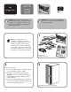
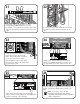
Fibre Channel
Cable Connection
Attach a Fibre Channel cable (one for every two
drives) to the e2400-160 interface controller. If you
are only attaching one cable, attach it to port 0.
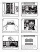
21 22
23 24
25
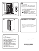
If necessary, loop the cable and bind it with a white
tie wrap in the cable channel to help take up any
slack.
Connect the cable to the Ethernet port on the
corresponding e2400-160 interface controller.
For example, connect the cluster controller card in drive
cluster 0 to the interface controller in slot 0 of the card
cage.
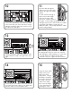
Locate the small cable clamp on the
upper right corner of the first cluster
frame. Using a #2 Phillips screwdriver,
remove the screw from the clamp.
Place the Ethernet cables in the clamp,
then secure the clamp to the cluster frame
by replacing the screw.
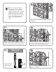
Attach a Fibre Channel cable to the e1200-160
robotics controller card located below the e2400-160
interface controller(s) in the card cage.
Route the cable(s) through access holes on the top or
bottom of the library cabinet and to a switch or an
HBA.
Note: If necessary, refer to the HP
StorageWorks ESL E-series Tape Library
Unpacking and Installation Guide for detailed
cabling configurations.
26