
Compaq StorageWorks Data Replication Manager HSG80 ACS Version 8.5P Operations Guide

Configuring a Data Replication Manager Solution 4–31
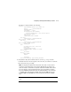
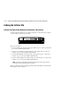
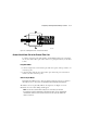
Figure 4–8. Cabling between the controllers and switches
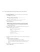
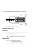
Connect the Initiator Site to the External Fiber Link
Locate the connection points at the initiator site that link the initiator site to the target
site. Look for either a fiber optic cable connector or a patch panel where you can insert
a cable.
Long Wave GBICs
1. Connect a single-mode, 9-micron fiber optic cable from port 6 of the top switch to one
connection point.
2. Connect another single-mode, 9-micron fiber optic cable from port 6 of the bottom
switch to the other connection point.
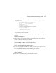
Other Transport Modes
Data Replication Manager uses other long distance transport modes. For connection
information, refer to our website at:
http://www.compaq.com/products/storageworks/.
The initiator site is now physically linked to the target site. See Figure 4–9 for an
illustrated view of how this cabling should appear.
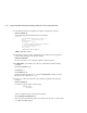
NOTE: You can make sure that switches and ports are connected as you have them
documented by issuing the nbrStateShow command at the switch. Issue the topologyShow
command at the switch to reveal if you have more than one fibre optic cable between the
switches on each site.
CXO7089A
1
2
3
4